


OFF
GO LOCAL
| Company | Stock | Price |
|---|---|---|


MIKROE-6126
19 g
Status:
Step Down 12 Click is a compact add-on board for reliable DC-DC step-down applications. Based on Texas Instruments' TPS62902 synchronous step-down converter, it features the DCS-Control topology, which combines hysteretic, voltage mode, and current mode control for precision and fast response to voltage changes. Supporting a wide input voltage range of 3V to 17V, it provides stable output voltages with accuracy within ±1% and can enter power save mode for high efficiency under light loads. With 16 configurable output voltages from 0.7V to 5.5V, this Click board™ is ideal for applications in factory automation, building systems, data centers, enterprise computing, and motor drives where efficient, stable power conversion is essential.
Step Down 12 Click is fully compatible with the mikroBUS™ socket and can be used on any host system supporting the mikroBUS™ standard. It comes with the mikroSDK open-source libraries, offering unparalleled flexibility for evaluation and customization. What sets this Click board™ apart is the groundbreaking ClickID feature, enabling your host system to seamlessly and automatically detect and identify this add-on board.
This product is no longer in stock
Availability date:
OFF
| Company | Stock | Price |
|---|---|---|
Step Down 12 Click is based on the TPS62902, a synchronous step-down DC-DC converter from Texas Instruments. This converter uses the DCS-Control topology, an advanced control architecture that merges the strengths of hysteretic, voltage mode, and current mode control. DCS-Control enables rapid response to output voltage changes by sending feedback to a fast comparator stage, ensuring constant switching frequency under stable conditions and fast adaptability during dynamic load changes. This Click board™ accommodates a wide input voltage range from 3V to 17V through its VIN terminal, making it suitable for various standard power sources, including 12V supply lines, single or multiple Li-Ion cells, and 5V or 3.3V rails. It is suitable for numerous use cases, including factory automation, building automation, data center systems, enterprise computing, motor drive applications, and beyond.
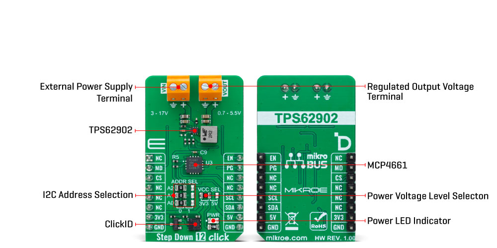
It is designed with precision and delivers an output voltage accuracy of ±1% due to its DCS-Control-based regulation. Additionally, the TPS62902 enters power save mode during light loads to maximize efficiency, backed by a low quiescent current of just 4µA, ideal for energy-conscious applications. This Click board™ integrates the MCP4661, enabling the host MCU to configure 16 fixed output voltages on the VOUT terminal, adjustable from 0.7V to 5.5V. The MCP4661 communicates through a 2-wire I2C interface that supports clock speeds up to 3.4MHz, with I2C addresses adjustable via the onboard ADDR SEL jumpers.
The MD pin allows users to select the TPS62902’s operational mode, enabling flexible configuration. This pin offers options for fixed PWM or automatic PFM/PWM mode with AEE functionality and settings for switching frequency, internal/external feedback, output discharge, and PFM/PWM selection. The EN pin functions as the converter’s enable control, while the PG (Power Good) pin is an open-drain signal to confirm if the output voltage has reached its target. It also indicates when the device is turned off due to undervoltage lockout (UVLO) or thermal shutdown, enhancing system protection and operational feedback.
This Click board™ can operate with either 3.3V or 5V logic voltage levels selected via the VCC SEL jumper. This way, both 3.3V and 5V capable MCUs can use the communication lines properly. Also, this Click board™ comes equipped with a library containing easy-to-use functions and an example code that can be used as a reference for further development.
Type
Buck
Applications
Ideal for applications in factory automation, building systems, data centers, enterprise computing, and motor drives
On-board modules
TPS62902 - synchronous step-down DC-DC converter from Texas Instruments
Key Features
DC-DC step-down conversion, DCS-control topology, wide input voltage range, 16 selectable fixed output voltages, high accuracy, power save mode, operational mode selection, power-good indication, and more
Interface
GPIO,I2C
Feature
ClickID
Compatibility
mikroBUS™
Click board size
M (42.9 x 25.4 mm)
Input Voltage
3.3V or 5V,External
This table shows how the pinout on Step Down 12 Click corresponds to the pinout on the mikroBUS™ socket (the latter shown in the two middle columns).
| Notes | Pin | Pin | Notes | ||||
|---|---|---|---|---|---|---|---|
| NC | 1 | AN | PWM | 16 | EN | Device Enable | |
| Mode Selection | MD | 2 | RST | INT | 15 | PG | Power-Good Indicator |
| ID COMM | CS | 3 | CS | RX | 14 | NC | |
| NC | 4 | SCK | TX | 13 | NC | ||
| NC | 5 | MISO | SCL | 12 | SCL | I2C Clock | |
| NC | 6 | MOSI | SDA | 11 | SDA | I2C Data | |
| Power Supply | 3.3V | 7 | 3.3V | 5V | 10 | 5V | Power Supply |
| Ground | GND | 8 | GND | GND | 9 | GND | Ground |
| Label | Name | Default | Description |
|---|---|---|---|
| LD1 | PWR | - | Power LED Indicator |
| JP1 | VCC SEL | Left | Power Voltage Level Selection 3V3/5V: Left position 3V3, Right position 5V |
| JP2 | ADDR SEL | Left | I2C Address Selection 0/1: Left position 0, Right position 1 |
| Description | Min | Typ | Max | Unit |
|---|---|---|---|---|
| Supply Voltage | 3.3 | - | 5 | V |
| External Power Supply | 3 | - | 17 | V |
| Output Voltage | 0.75 | - | 5.5 | V |
We provide a library for the Step Down 12 Click as well as a demo application (example), developed using MIKROE compilers. The demo can run on all the main MIKROE development boards.
Package can be downloaded/installed directly from NECTO Studio Package Manager (recommended), downloaded from our LibStock™ or found on MIKROE github account.
Library Description
This library contains API for Step Down 12 Click driver.
Key functions
stepdown12_get_pg_pin This function returns the power good (PG) pin logic state.
stepdown12_set_vout This function sets the voltage output by setting the digipot wiper resistance.
stepdown12_enable_device This function enables the device by setting the EN pin to high logic state.
Example Description
This example demonstrates the use of Step Down 12 Click by changing the output voltage every 3 seconds.
void application_task ( void )
 {
     static float vout = STEPDOWN12_VOUT_MAX;

     if ( !stepdown12_get_pg_pin ( &stepdown12 ) )
     {
         log_error( &logger, " Power Good Fault - Vout is below nominal regulationrn" );
     }

     if ( STEPDOWN12_OK == stepdown12_set_vout ( &stepdown12, vout ) )
     {
         log_printf( &logger, " Vout: %.3f Vrnn", vout );
         vout -= 0.5;
         if ( vout < STEPDOWN12_VOUT_MIN )
         {
             vout = STEPDOWN12_VOUT_MAX;
         }
     }
     Delay_ms ( 3000 );
 }
The full application code, and ready to use projects can be installed directly from NECTO Studio Package Manager (recommended), downloaded from our LibStock™ or found on MIKROE github account.
Other MIKROE Libraries used in the example:
Additional notes and informations
Depending on the development board you are using, you may need USB UART click, USB UART 2 Click or RS232 Click to connect to your PC, for development systems with no UART to USB interface available on the board. UART terminal is available in all MIKROE compilers.
This Click board™ is supported with mikroSDK - MIKROE Software Development Kit. To ensure proper operation of mikroSDK compliant Click board™ demo applications, mikroSDK should be downloaded from the LibStock and installed for the compiler you are using.
For more information about mikroSDK, visit the official page.
NOTE: Please be advised that any peripheral devices or accessories shown connected to the Click board™ are not included in the package. Check their availability in our shop or in the YMAN section below.

$889.00

$95.00

$549.00

$299.00

$29.00

$29.00

$3.30

$3.60

$119.00

$349.00

$349.00

$349.00

$299.00

$449.00

$269.00

$249.00

$209.00
