


OFF
UNI-DS v8 with on-board CODEGRIP over USB-C and WiFi
PID: MIKROE-5157
Weight: 1900 g


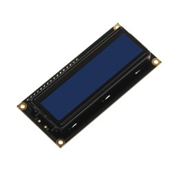
Character LCD 2x16 with blue backlight

MCU CARD 23 for STM32 STM32F767BI

SiBRAIN for STM32F732IE

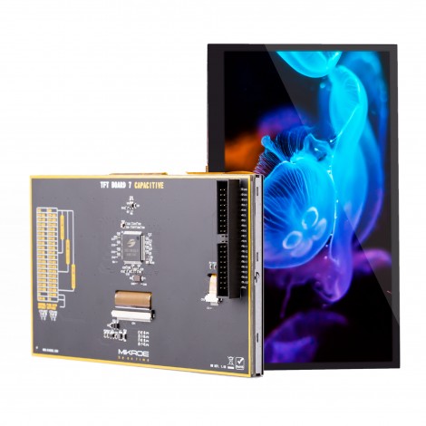
TFT Board 5 Capacitive With Bezel

UNI-DS v8
$889.00
$889.00


Universal development board
UNI-DS development board integrates CODEGRIP - the world's first programmer & debugger over WiFi and USB-C. This feature allows unlimited possibilities for development.
*CODEGRIP WiFi License is available as an additional feature.
CODEGRIP enables you to place UNI-DS development board in almost any hardly accessible places such as hazardous environments, agricultural settings, and high-rise buildings while still retaining full debugging and programming access.

Debugging over WiFi enables our technical support to directly access the user's hardware and solve the problem. Replicating a user's hardware is no longer a challenge.

CODEGRIP debugger & programmer over WiFi and USB-C currently supports more than 3300 microcontrollers from different vendors. And you get lifetime free updates with new microcontrollers and vendors.
CODEGRIP Suite is a powerful software suite that offers complete control over the UNI-DS development board. It is used to intelligently manage programming and debugging tasks, as well as various other options and settings of the development board.
USB-C debugger enables effortless programming/debugging over a generic USB driver connection without the need for additional driver support.

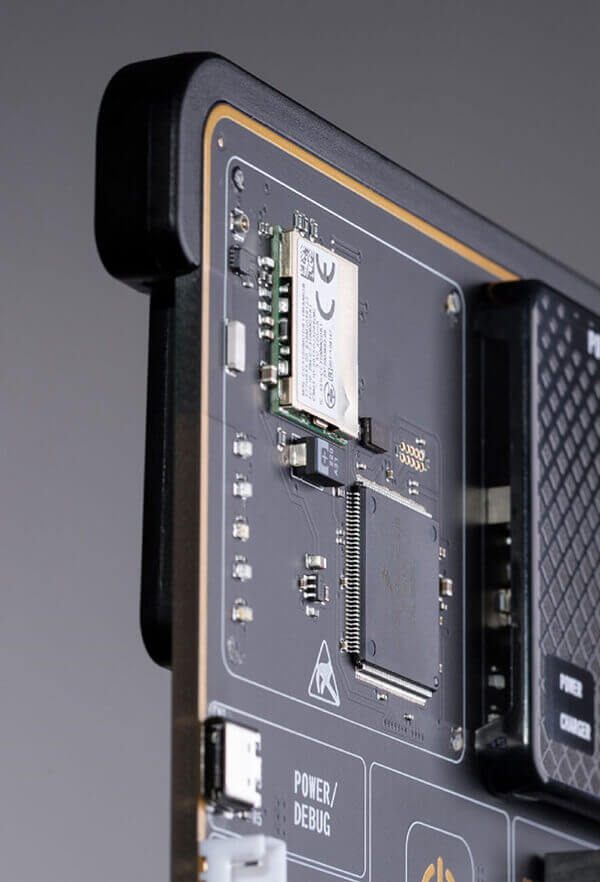
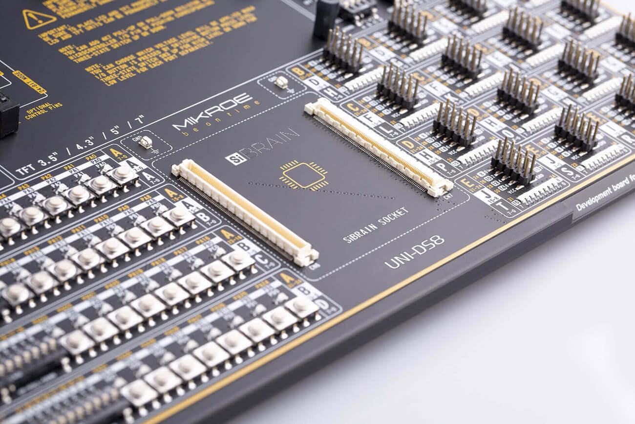
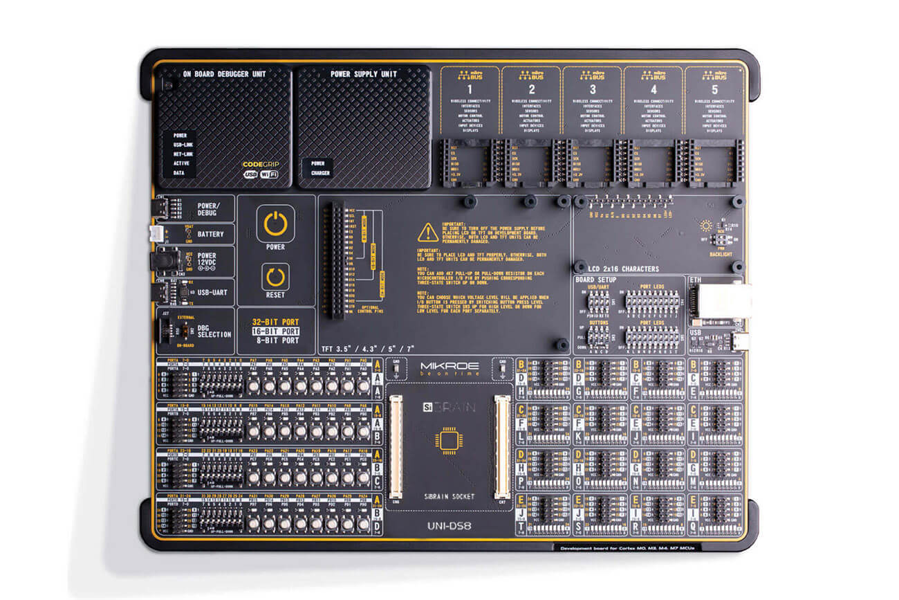
The SiBRAIN socket facilitates extremely simple installation and replacement of a microcontroller (MCU) or processor on a development board. It allows absolute compatibility between the development board and any supported MCUs and processors, regardless of their pin number and architecture.

SiBRAIN standard allows working with microcontrollers from low pin count to high pin count on one board.
The UNI-DS development board is sold without a SiBRAIN add-on board. Choose from over 100 SiBRAIN add-on boards available now in our shop.

The SiBRAIN standard currently supports 3300+ microcontrollers from different vendors: Microchip, STMicroelectronics, Texas Instruments, and NXP, with even more vendor support coming soon.

The UNI-DS development board features a new display connector. The new connector has female 2x20-pin support allowing different resolutions, screen sizes, and technologies. Currently there are 16 high-quality TFT display boards to choose from.

The display board connector can be attached with various screen technologies. Currently available are the TFT capacitive and resistive boards. Future iterations will offer technologies such as OLED and e-Ink.

Check out how your project looks on different screen sizes and resolutions. Choose from 3", 4", 5" and 7" displays with different resolutions - 320x240, 480x272 and 800x480 pixels.
Rapid prototyping allows the engineer to take the most efficient and effortless way to envision the design ideas, capabilities, and limitations through measurable means. This is the crucial eliminating factor for time to market pressure.

The UNI-DS offers five improved mikroBUS™ sockets, , where you can place any of the 827 different Click boards™. This gives you infinite possibilities with the largest add-on board selection in the world.
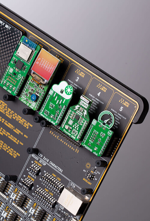
With 827 Click boards™ available, they are the fastest-growing range of add-on boards in the world. They enhance rapid development and accelerate time to market. These ready-to-use boards require no additional hardware configuration and save engineers time for testing and troubleshooting often associated with the prototyping phase.

The ready-to-use 827 Click boards™ are saving time and money by offering complete hardware and software solutions instead of developing them from scratch. Choose one of the hundreds of Click boards™ out of these categories: mixed-signal, wireless connectivity, storage, interface, displays, human-machine interface, adapter, clock and timing, motor control, power management, and audio & voice.

UNI-DS offers a state-of-the-art power supply with constant power delivery and unprecedented flexibility. The power supply module is carefully designed to regulate, filter, and distribute the power noise-free.
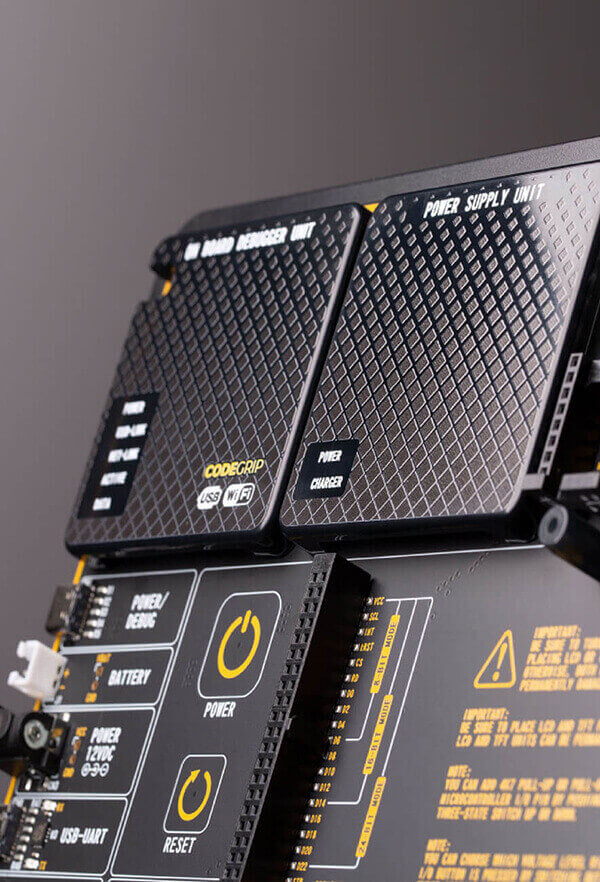
In addition, it features convenient capacitive POWER and RESET buttons.
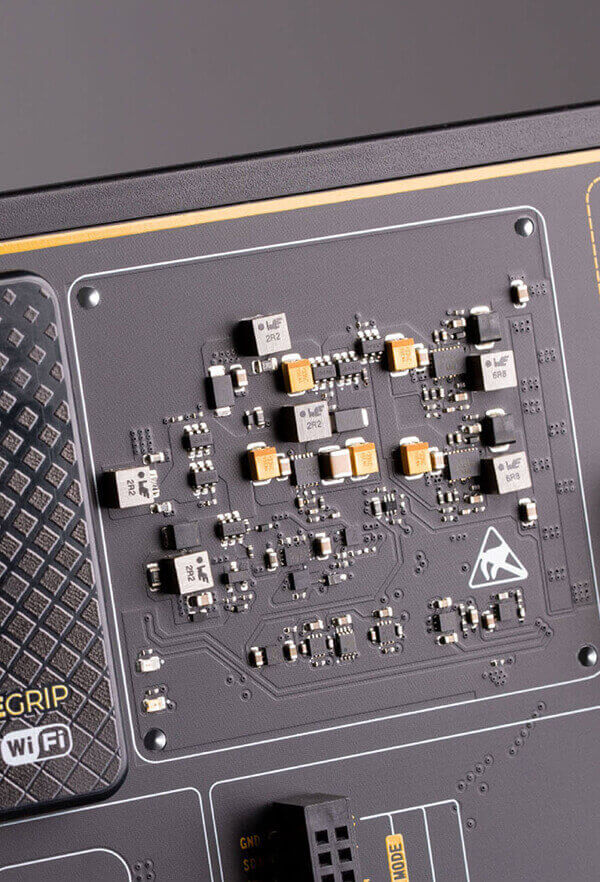
The power supply unit supports a wide range of power sources that can be used: External 12VDC, USB, and a Li-Po/Li-ION battery. It also supports UPS functionality. When powered by the battery, it offers an ultimate degree of autonomy.
The power supply module supports programmable voltage output, which can be used as a reference for various purposes, including A/D or D/A converters, comparators, and any other peripherals that require or can use an external reference voltage. The programmable voltage output can be controlled over the CODEGRIP Suite.

The UNI-DS development board is 3.2 mm thick. Its sturdy and durable design prevents bending during population and installation. All board components are produced to surface-mounted technology standards, enabling a rugged and compact design.

Every detail is carefully thought through, from the height-adjustable stand with non-slip pads to the ergonomic design, allowing comfortable project development.

UNI-DS has a clean and elegant design, allowing the user to instantly understand how to set it up and tune it according to needs easily. The development board is divided into several sections, arranged so that all the related interactive components, such as switches, buttons, indicators, and connectors, are logically positioned and grouped.


OFF
PID: MIKROE-5157
Weight: 1900 g
OFF
PID: MIKROE-5305
Weight: 1900 g
5 10 20
Quantity discount
SAVE:
Was:
Total Save:


Secure online payments provided by 2Checkout.com, Inc.
All credit card and personal details are kept secure, and our customer
list is not disclosed to any third party.


OFF
PID: --
Weight: --
5 10 20
Quantity discount
SAVE:
Was:
Total Save:

Programming over WiFi is a unique feature of CODEGRIP, enabling users to program the MCU from a remote location. Combined with the ability to be powered from the target device, this allows programming and debugging to be performed completely wirelessly. However, this is an optional feature of CODEGRIP and requires a WiFi license.
After you purchase a WiFi license for CODEGRIP you will receive an email with license registration code and instructions to activate this feature in your CODEGRIP. Single WiFi licence can be used only once, thus unique WiFi license is required per CODEGRIP.
OFF
PID: MIKROE-3517
5 10 20
Quantity discount
SAVE:
Was:
Total Save:

Secure Socket Layer (SSL) is a standard security technology for establishing an encrypted link between a server and a client. It enables encryption of TCP data traffic, ensuring a high level of protection. CODEGRIP offers feature to encrypt communication using SSL, preventing any unauthorized access during the programming or debugging over WiFi.
After you purchase an SSL license for CODEGRIP you will receive an email with license registration code and instructions to activate this feature in your CODEGRIP. Single SSL licence can be used only once, thus unique SSL license is required per CODEGRIP.
OFF
PID: MIKROE-3599
5 10 20
Quantity discount
SAVE:
Was:
Total Save:
OFF
PID: --
Weight: --
5 10 20
Quantity discount
SAVE:
Was:
Total Save:
Status: Out of Stock
The complete board area is divided into several sections, arranged so that all the related components, switches, buttons, indicators, and connectors are logically positioned and grouped together.

The powerful CODEGRIP module, an universal programmer/debugger, supports a wide range of different MCUs, produced by several major chip vendors. It allows in-place programming and debugging of all supported microcontrollers, offering many options, offering many useful programming/debugging options, seamless integration with the Mikroe software environment, and some powerful and unique features such as the programming/debugging over WiFi; a feature that will revolutionize the way embedded applications are developed.
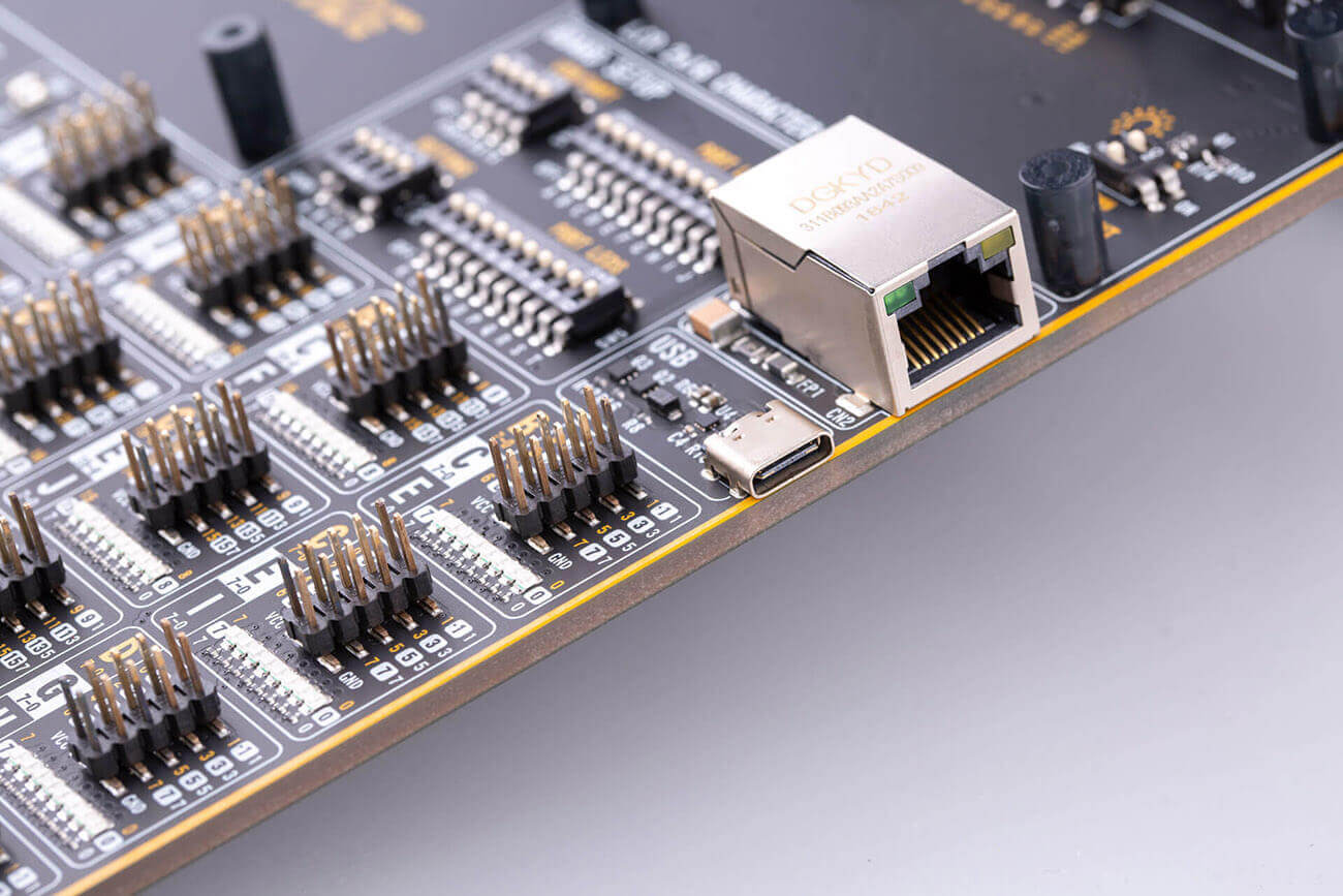
The CODEGRIP module uses the USB-C connector for a reliable and secure connection with the personal computer (host PC). It does not require any additional drivers because it utilizes an HID driver model, natively supported by the computer's operating system. The USB-C connector is also used to power the development board, simplifying the cable management. CODEGRIP module is supported by CODEGRIP Suite.
The power supply module provides a clean, regulated voltage for the development board. It can use a wide range of external power sources, including a battery, an external 12V power supply, and a power source over the USB Type-C connector.
It supports the power OR-ing function for uninterrupted operation.
The development board is equipped with two touch-sensitive buttons labeled as POWER and RESET. These buttons are used to power up the board and reset the MCU. The advanced design of the power supply module allows several types of power sources to be used, offering unprecedented flexibility: when powered by a Li-Po/Li-Ion battery, it offers an ultimate degree of autonomy.
Five improved mikroBUS™ sockets, allowing interfacing with a vast amount of electronic circuits and reference designs, standardized under the Click board trademark.
Click boards™ are simple to use,require no additional hardware configuration and can be easily connected to the development board by inserting them into any of the available mikroBUS™ sockets
A new design of the mikroBUS™ socket allows even easier interfacing with the Click board™ line of products: it has a sturdier design which helps aligning the Click board™ correctly.

The Power button is a touch sensitive button used to power up the development board. Its sleek design and flawless responsiveness add up to the whole experience. The touch sensitive button is resistant to wear over time and it does not exhibit any bouncing effect, unlike the mechanical switches.
As soon as a valid power source is connected, the development board will enter the Stand-By mode. When the capacitive POWER button is pressed, the PSU module will start distributing the power to the rest of the development board. Below the POWER capacitive button, there is a RESET capacitive button which is not entirely power-related, but it has a similar function: it is routed to the MCU reset pin. Pressing this button will trigger a reset of the host MCU.
UNI-DS8 development board features a standardized 2x20-pin display connector. This connector consists
of the 8080 parallel interface, offering support for displays with up to 8 bits per color (up to
24-bit mode, 16 million colors). Besides the 8080 interface, this connector also contains pins
related to touch panel controller, interfaced over dedicated I2C bus lines. The power supply rails
are also routed to this connector.
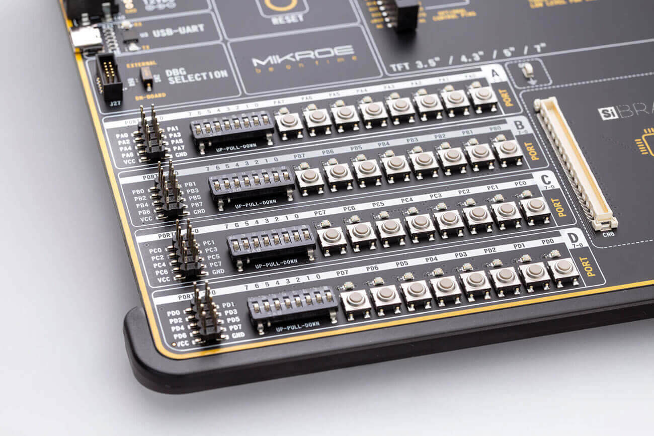
UNI-DS8 supports 2x16 characters LCD module, connected in
4-bit mode. It offers a dedicated 1x16-pin header that can host a compatible 1x16 characters LCD.
Each pin of the connector is labeled on the development board and should be connected with the
respective pin of the LCD.
UNI-DS8 development board offers the UART connectivity over the USB-C connector by utilizing the
FT230XQ, a popular USB-UART bridge IC, produced by FTDI Chip. This IC contains the complete USB
stack necessary for the interface bridging between the UART peripheral of the MCU and the USB
interface of the PC. FT230XQ drivers are available for download from the UNI-DS8 product web page,
as well as from the official FTDI drivers download web page. To enable data exchange via the USB-UART
connector, the MCU UART peripheral lines must be connected to the corresponding pins of the FT230XQ
IC. This can be done using the four-pole DIP switch, labeled as USB/UART.
USB is a very
popular industry standard that defines cables, connectors, and protocols used for communication and
power supply between devices. USB-C (USB Type-C connector) is the latest version of the USB
connector, developed by the USB Implementation Forum (USB-IF).

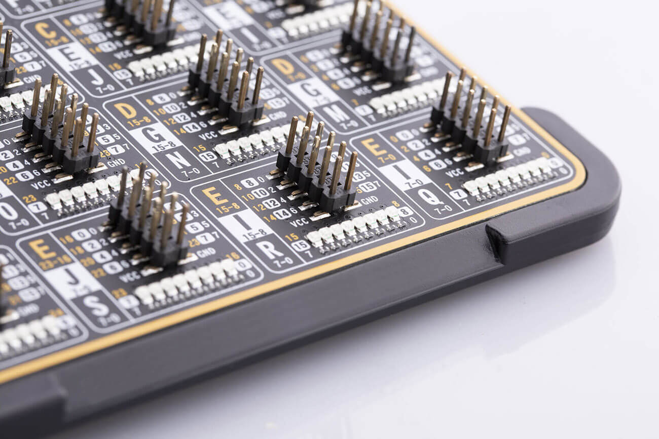
The I/O (Input/Output) section occupies the lower part of the development board and contains available MCU pins routed to 2x5-pin headers for easy access. Some of them are equipped with configurable pull-up or pull-down resistors and buttons for applying logic states to MCU pins, while all of them are equipped with LED indicators. Pins are divided into groups following the grouping concept used on the MCU itself. This section is where the most interaction with the MCU takes place. MCU cards have their ports routed as either 8-bit, 16-bit or 32-bit ports.
UNI-DS8 development board is supported by a powerful CODEGRIP Suite, offering complete control over the UNI-DS8 development board. It is used to intelligently manage programming and debugging tasks, and to configure various other options and settings, providing visual feedback through its clean and comprehensive Graphical User Interface (GUI). To better understand how to operate and configure UNI-DS8 development board and its integrated CODEGRIP module, a separate manual is provided on this link.


| Architecture | Universal,ARM (32-bit),AVR (8-bit),dsPIC/PIC24 (16-bit),PIC (8-bit),PIC24/dsPIC33 (16-bit),PIC32 (32-bit), SiBRAIN card dependent |
| Programming | USB,WiFi |
| Silicon Vendor | Microchip,Universal,Texas Instruments,STM,NXP,GigaDevice |
| MCU Socket | MCU card 8th gen |
| mikroBUS No. | 5 |
| Supply Voltage | Battery, USB,External |
| Category | 8th Generation,Universal Boards |

$15.00
$11.76

$9.48

$9.48

$14.88

$10.80


Share Product
Share this product with your clients and friends.