


In the world of electronics, prototyping is a crucial step. It's where ideas take physical form.
Breakout boards play a pivotal role in this process. They are the unsung heroes of electronic design.
These handy tools simplify the use of complex integrated circuits. They provide easy access to a chip's functionality, making prototyping more efficient.
From hobbyists to professional engineers, breakout boards are a staple. They allow for quick testing and iteration of designs, saving time and resources.
This article delves into the world of breakout boards. It explores their benefits, types, key features, and how to integrate them into your projects.
Whether you're a seasoned designer or a beginner, you'll find valuable insights here. Let's enhance your prototyping process with breakout boards.
Introduction to Breakout Boards
Breakout boards are integral components in electronics design, particularly in prototyping. They act as intermediaries that simplify the use of complex and miniature integrated circuits (ICs).
These boards make the pins of an IC more accessible by converting them into a user-friendly format. This setup greatly eases the process of connecting ICs to other components within a circuit.
Typically, ICs are designed with a size constraint, making it difficult to solder or connect directly to other parts. Surface-mount technology (SMT), for example, can be particularly challenging due to tiny leads. Breakout boards address this issue by converting SMT components into breadboard-friendly layouts, allowing easy soldering and connection to other parts.
In essence, breakout boards extend an IC’s pins, breaking out the connections into a larger, more manageable form factor. They often feature labeled pins, which eliminate guesswork and reduce the chances of making errors during integration. This simplifies the initial stages of development and testing significantly.
Their versatility is remarkable. They accommodate everything from sensors and microcontrollers to communication modules. You can quickly swap components and experiment with different setups without the tedious work of constructing custom PCBs from scratch. This capability is especially useful during the early phases of project development when flexibility is key.
Breakout boards are also valuable in educational settings. They provide students and beginners with a practical way to learn about electronics and circuit design. By using these boards, learners can focus on understanding circuit behavior rather than struggling with physical connections and soldering.
Overall, breakout boards have transformed the prototyping landscape. They offer a practical solution to handling complex components, providing a bridge between conceptual design and physical testing. Their ability to simplify complex circuits boosts efficiency, fostering innovation and experimentation in the field of electronics.
Advantages of Using Breakout Boards in Prototyping
Simplifying Circuit Designs
Breakout boards are invaluable tools for simplifying circuit designs in prototyping. They remove the complexity associated with handling small or intricate integrated circuits. Many ICs have dozens of pins tightly packed on tiny packages, which can make connections challenging.
Breakout boards solve this problem by extending these pins to a more manageable size and spacing. This conversion facilitates easy connections with other electronic components, making the entire design process more straightforward.
Moreover, breakout boards provide access to all the necessary functionalities of a chip. The labeled pins on the board guide users, eliminating any potential for misconnection. This feature alone reduces the possibility of errors, ensuring a smoother and faster prototyping phase. By providing a standard interface, breakout boards allow easy integration with existing designs, removing the need for intricate custom wiring.
The ease of use provided by breakout boards is a significant advantage, especially for those working on complex projects. Instead of spending time on manual configurations, engineers and hobbyists can focus on developing innovative solutions. This shift ensures valuable time is spent on design creativity rather than on troubleshooting connectivity issues.
Reducing Complexity
In the realm of prototyping, reducing complexity is crucial. Breakout boards offer a simplified approach to handling intricate circuits, minimizing the need for complex wiring. This reduction is particularly beneficial when working with surface-mount devices, which can be daunting due to their size and pin density. By converting these components into more accessible formats, breakout boards make it easier for anyone to work with them without specialized equipment.
The added benefit of standardization cannot be understated. Breakout boards often come with consistent pin layouts and configurations, which help in reducing learning curves. Engineers can effortlessly integrate various components, accelerating the transition from concept to functional prototype. This streamlined process enables faster project iterations, resulting in quicker delivery of effective solutions.
Breakout boards also help consolidate scattered connections, making them more manageable. This organized approach reduces the likelihood of errors. By minimizing the complexity, engineers can focus on refining other critical design aspects, such as performance and functionality. Ultimately, breakout boards demystify the electronics prototyping process by addressing the intricacies that often deter beginners from tackling ambitious projects.
Quick Testing and Feedback
The ability to quickly test and receive feedback is vital during prototyping. Breakout boards play a pivotal role in enabling rapid experimentation with various components. When developers need to swap out parts or test different configurations, breakout boards facilitate these changes without a hassle. This convenience accelerates the testing phase and supports frequent iterations, allowing designers to refine their projects efficiently.
Moreover, breakout boards allow for immediate analysis of component behaviors in real-world conditions. Developers can plug the boards into a breadboard or connect them to other devices to test functionality on the spot. Such hands-on evaluation helps identify issues and confirms the effectiveness of designs early in the process. This real-time feedback loop significantly boosts the development speed and reduces time-to-market.
In addition, developers can explore new technologies and components with less risk. They can experiment with cutting-edge sensors, microcontrollers, and communication modules, thanks to the versatility of breakout boards.
This exploratory advantage ensures that the latest innovations are accessible, fostering a culture of continuous innovation. By streamlining the testing and feedback cycles, breakout boards facilitate faster learning and adaptation, which are crucial in today’s fast-paced technological environment.
Types of Breakout Boards
Standard Breakout Boards
Standard breakout boards serve as the foundational tools in the world of electronics prototyping. They typically cater to generic integrated circuits and components widely used across various projects. These boards are designed with user-friendliness in mind. They bring complex pin layouts into a simpler format, making connections easy. Users can expect a straightforward setup process with minimal technical hurdles.
Standard boards often feature clear labeling to guide users in interfacing components correctly. This aspect is crucial for beginners and professionals alike, ensuring accurate connections without extensive research or guesswork.
Common components that are found on standard breakout boards include basic sensors, microcontrollers, and logic chips. Their availability and affordability make them indispensable in educational settings as well, providing students with practical exposure to circuit design and functionality.
The versatility of standard breakout boards is a key benefit. They find applications in a broad spectrum of projects, from simple DIY electronics to more advanced prototypes. Their general-purpose nature allows them to bridge the gap between conceptual understanding and practical implementation, offering a reliable, efficient way to bring ideas to life.
Specialized Add-on Boards
Specialized add-on boards are tailored for specific components or applications, providing unique functionalities that standard boards might not offer. These boards are crafted to meet specialized needs in certain projects or research. Unlike their standard counterparts, they often include integrated features like voltage regulators or communication interfaces, designed for niche applications.
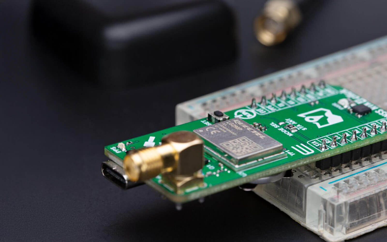
Add-on boards are particularly beneficial when working with advanced technologies such as GPS modules, Bluetooth chips, or accelerometers. These boards provide enhanced capabilities like built-in antennas or pre-configured communication protocols to simplify the development process. They allow developers to focus on integrating these specialized components without dealing with underlying complexities.
By using specialized add-on boards, engineers and hobbyists can explore cutting-edge technologies with ease. These boards cater to the innovative edge, empowering users to develop sophisticated prototypes, such as IoT devices or custom robotics components. In essence, specialized add-on boards extend the reach of what is possible with electronics prototyping, allowing for exploration beyond the limits of standard configurations.
Key Features of Breakout Boards
Pin Configuration
Pin configuration is a critical feature of breakout boards, impacting usability and functionality. Clear and well-organized pin layouts simplify the connection process, making it accessible for users at all skill levels. Each pin is typically labeled to indicate its function, reducing the chance of errors during setup.
Breakout boards often feature standardized pin headers, allowing seamless integration with breadboards. This compatibility is vital for testing and prototyping, enabling quick and easy component swaps. The layout can vary, accommodating different components, from simple sensors to complex processors.
Furthermore, some breakout boards include additional features like decoupling capacitors or pull-up resistors directly on the board. These integrated elements support various electronic designs by stabilizing voltage and simplifying circuit layouts. This thoughtful design ensures that even complex components can be used effectively and efficiently, encouraging experimentation and innovation.
Size and Form Factor
The size and form factor of breakout boards are crucial for their integration into projects, especially those with space constraints. Typically compact, these boards are designed to occupy minimal space while providing maximum functionality. Their reduced size allows for dense, efficient circuit layouts without compromising accessibility.
Despite their small dimensions, breakout boards can still support numerous features, including multiple pinouts and onboard components. This compactness is often achieved through efficient board design, making them suitable for both large-scale and small-scale projects.
Form factors can vary from rectangular to more specialized shapes, dictated by the component they accommodate. This diversity in design allows for custom fits within a wide range of applications, from hobbyist projects to industrial prototypes. The balance between size and functionality helps optimize overall project design, enabling creativity without spatial limitations.
Mounting Options
Mounting options for breakout boards are essential considerations for their seamless integration into various projects. These options range from through-hole mounts to surface-mount techniques, offering flexibility based on project requirements. Through-hole mounts are favored in prototyping, providing sturdy and reliable connections.
Surface mount options cater to projects where space conservation is critical, offering a sleek profile suitable for compact designs. Additionally, some breakout boards come with adhesive backing for quick, tool-free placement, which is ideal for temporary setups or iterative testing phases.
For more permanent applications, breakout boards may include screw holes or mounting brackets. These provide secure attachment points, ensuring stability even in dynamic environments. By offering a variety of mounting techniques, breakout boards can adapt to diverse electronic designs, enhancing their versatility and application range while ensuring robustness and ease of use.
Integrating Breakout Boards in Projects
Step-by-Step Setup
Incorporating breakout boards into projects requires a systematic approach. The first step is selecting the right board for your component. Consider the board's compatibility with other parts, ensuring pin configurations and voltage levels align with your needs.
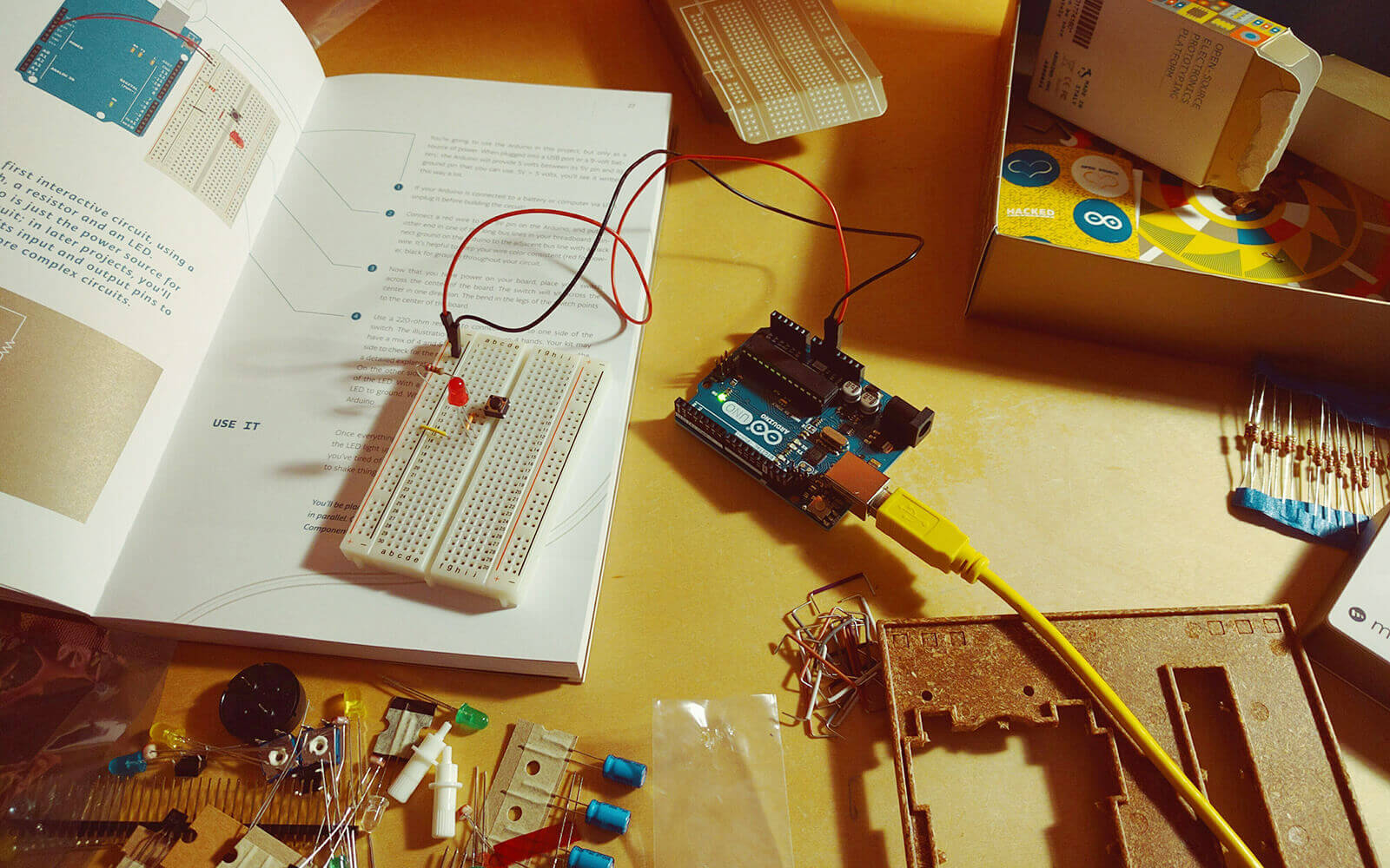
Once chosen, prepare your workspace. Gather all necessary tools and safety equipment. It's important to have a clear, organized workspace to prevent mistakes. Begin by placing the breakout board on a breadboard, aligning pins properly for easy connections.
Next, connect the breakout board to your microcontroller or main circuit using jumper wires. Carefully follow the schematic for accurate placement, paying attention to details like VCC and ground connections. Secure your wires to ensure reliable connections, avoiding accidental disconnections during testing.
Finally, power up the setup and run initial tests. Monitor system performance, checking for response from all components. This phase may involve tweaking connections or adjusting code to achieve desired results. Methodical testing ensures the project works as intended, paving the way for further developments.
Best Practices for Soldering
Soldering is a crucial skill when working with breakout boards, and doing it well ensures robust connections. Start by selecting appropriate soldering tools, including a quality soldering iron with adjustable temperature settings. Use lead-free solder for safer and environmentally friendly practices.
Before soldering, ensure both components and breakout boards are clean and free from any contaminants. Dirt can hinder effective soldering, leading to weak connections. Pre-tin the soldering iron tip and the component leads. This involves applying a small amount of solder for better adhesion.
When soldering, maintain a steady hand to avoid bridging connections between pins. Use the iron to heat both the pad and the pin simultaneously, then apply solder. Remove the iron promptly once solder flows smoothly. This technique minimizes heat exposure, protecting sensitive components from damage.
Post-soldering, inspect connections for quality. Look for shiny, smooth joints without blobs or gaps. If necessary, use a solder wick to remove excess solder and refine joints. By following these practices, you ensure strong, reliable connections that enhance the performance and longevity of your electronic project.
Challenges and Considerations
Compatibility Issues
One common challenge with breakout boards is compatibility. Not all breakout boards work with every microcontroller or system. Mismatches in voltage levels or communication protocols can lead to issues. For instance, a board might require a 3.3V signal, while your system operates at 5V. Such disparities can cause malfunction or damage.
To prevent this, carefully review the specifications of both the breakout board and the host device. Ensure that the logic levels match and that the pin configurations align with each other. Use level shifters if necessary to bridge voltage differences between components.
Additionally, consider software compatibility. Some breakout boards come with libraries or example code. Check if these resources are available and compatible with your development environment. Testing the setup early can reveal compatibility issues, allowing adjustments before moving further in the project development phase.
Sourcing Quality Components
Finding high-quality breakout boards is essential for reliable performance. Not all suppliers offer components that meet industry standards. Poor-quality boards can have defects likem improper soldering or incorrect pin labeling. These defects can disrupt your project or lead to failures.
To source quality components, rely on reputable suppliers known for their stringent quality controls. Look for reviews and ratings from other users to gauge a supplier's reliability. Another useful approach is to select breakout boards from manufacturers that provide comprehensive documentation.
Inspect breakout boards upon receipt. Check for visible defects, ensuring all pins are correctly aligned and labels are clear. Testing each board before implementation can verify functionality and save you from future troubleshooting headaches. By being meticulous in sourcing, you reduce the risk of using subpar components in your projects.
Conclusion
Breakout boards are indispensable tools in electronics prototyping. They provide essential functionality and flexibility for engineers, hobbyists, and educators alike. These versatile components simplify the integration of complex circuits and enhance the efficiency of the design process.
Whether you're experimenting with a new sensor or building a custom interface, breakout boards offer a practical and cost-effective solution. Selecting the right board, understanding its features, and implementing best practices ensure a smooth development journey.
By adopting breakout boards in your projects, you can achieve innovation and expedite your prototyping endeavors. With this powerful tool, you're better equipped to transform ideas into tangible solutions.
Breakout Boards in Action: Products & Projects
Wondering how breakout boards can streamline your prototyping process? We’ve got you covered.
Explore our selection of breakout boards – our signature Click boards™, which are breakout boards with added structure, standardization, and plug-and-play simplicity. Whether you're accessing sensors, communication modules, or power interfaces, they make prototyping faster and cleaner.
 Smart NFC Click
 Current Sens Click
 ATA6505 Click
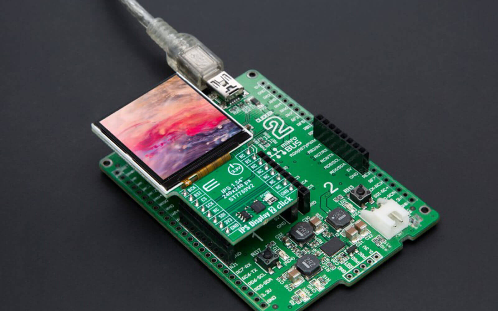
 IPS Display 2 Click
 Secure Tropic Click
 ISO ADC 7 Click
 EEPROM 16 Click
 Micro Pump Click
 Speaker 2 Click
 Rotary RGB Click
 RTC 21 click
 Solar Energy 3 Click - 1V8 Custom
Want to see breakout boards in real-world use? Dive into hands-on projects on EmbeddedWiki. Discover how engineers and makers are using breakout boards to build smarter systems, debug faster, and bring their ideas to life. Whether you're looking for tips or full project walkthroughs, it’s all just a click away.
ABOUT MIKROE
MIKROE is committed to changing the embedded electronics industry through the use of time-saving industry-standard hardware and software solutions. With unique concepts like Remote Access, One New Product/Day, Multi-Architectural IDE and most recently, the EmbeddedWiki™ platform with more than million ready-for-use projects, MIKROE combines its dev boards, compilers, smart displays, programmers/debuggers and 1800+ Click peripheral boards to dramatically cut development time. mikroBUS™; mikroSDK™; SiBRAIN™ and DISCON™ are open standards and mikroBUS only has been adopted by over 100 leading microcontroller companies and integrated on their development boards.
Your MIKROE


