


OFF
GO LOCAL
| Company | Stock | Price |
|---|---|---|


MIKROE-6078
23 g
Status:
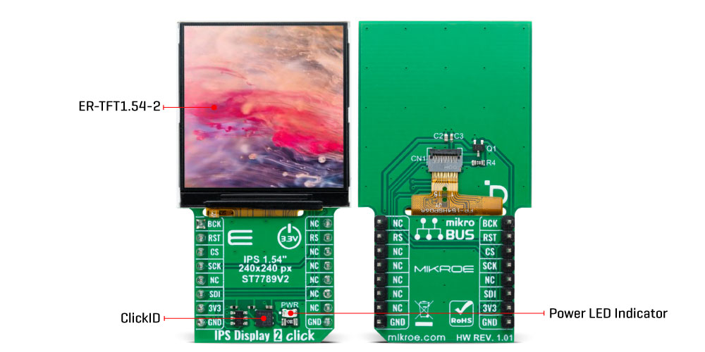
IPS Display 2 Click is a compact add-on board that displays high-resolution graphics in embedded applications. This board features the ER-TFT1.54-2, a 1.54" TFT LCD display from EastRising Technology, and uses the ST7789V2 controller for 262K color output. The display offers a 240x240 pixel resolution, operates through a 3-wire SPI interface, and includes additional control signals for precise display management. Its small form factor and high-resolution output make it suitable for various projects, including handheld devices, smart displays, and panels requiring clear visual output.
IPS Display 2 Click is fully compatible with the mikroBUS™ socket and can be used on any host system supporting the mikroBUS™ standard. It comes with the mikroSDK open-source libraries, offering unparalleled flexibility for evaluation and customization. What sets this Click board™ apart is the groundbreaking ClickID feature, enabling your host system to seamlessly and automatically detect and identify this add-on board.
This product is no longer in stock
Availability date:
OFF
| Company | Stock | Price |
|---|---|---|
IPS Display 2 Click is based on the ER-TFT1.54-2, a 1.54" TFT LCD display without a touch panel from EastRising Technology. Designed for high-resolution visual output, this display offers a crisp 240x240 pixel resolution, ideal for applications requiring clear and vibrant graphics. It connects through an 15-pin FPC connector with a 0.3mm pitch, ensuring stable communication with the host system. This board is suitable for projects requiring a compact, high-resolution screen, such as handheld devices, smart displays, or informational panels.
Though the display is not sunlight-readable, its compact design integrates it into various indoor applications. With a diagonal size of 1.54 inches, it boasts a compact form factor, featuring an outline dimension of 31.52mm (W) by 313.72mm (H) with the FPC folded and a thickness of just 1.9mm. The visual area of 28.72mm by 28.72mm ensures an optimal display experience, while the active area of 27.72mm (W) by 27.72mm (H) provides high precision in rendering content. The dot pitch of 0.1155mm by 0.1155mm guarantees fine detail in the display's output.
The ER-TFT1.54-2 is driven by the ST7789V controller, a highly integrated single-chip controller and driver specifically designed for 262K-color graphic TFT-LCDs, offering vibrant color depth and smooth graphical performance. This board operates through a 3-wire serial SPI interface, ensuring smooth communication between the display and the host MCU. Beyond the SPI interface pins, the display also uses additional control signals for enhanced functionality.
The RST pin plays a crucial role in ensuring reliable operation by allowing the display to be reset. This is essential for recovering from errors and initializing the display during power cycles. The BCK pin serves as a display backlight control, and the RS pin serves as a display data/command selection pin, crucial for distinguishing between data and command instructions sent via the SPI interface. This enables precise control over the display's functionality, ensuring that graphical content and operational commands are processed correctly.
This Click board™ can be operated only with a 3.3V logic voltage level. The board must perform appropriate logic voltage level conversion before using MCUs with different logic levels. Also, it comes equipped with a library containing functions and an example code that can be used as a reference for further development.
Type
Displays,TFT
Applications
Ideal for handheld devices, smart displays, and panels requiring clear visual output
On-board modules
ER-TFT1.54-2 - 1.54” TFT LCD display without touch panel from EastRising Technology
Key Features
1.54" TFT LCD display, 240x240 pixel resolution, SPI interface, compact dimensions, wide visual area, additional control lines for enhanced functionality, and more
Interface
SPI
Feature
ClickID
Compatibility
mikroBUS™
Click board size
L (57.15 x 25.4 mm)
Input Voltage
3.3V
This table shows how the pinout on IPS Display 2 Click corresponds to the pinout on the mikroBUS™ socket (the latter shown in the two middle columns).
| Notes | Pin | Pin | Notes | ||||
|---|---|---|---|---|---|---|---|
| Backlight Control | BCK | 1 | AN | PWM | 16 | NC | |
| Reset / ID SEL | RST | 2 | RST | INT | 15 | RS | Display Data / Command Selection |
| SPI Select / ID COMM | CS | 3 | CS | RX | 14 | NC | |
| SPI Clock | SCK | 4 | SCK | TX | 13 | NC | |
| NC | 5 | MISO | SCL | 12 | NC | ||
| SPI Data IN | SDI | 6 | MOSI | SDA | 11 | NC | |
| Power Supply | 3.3V | 7 | 3.3V | 5V | 10 | NC | |
| Ground | GND | 8 | GND | GND | 9 | GND | Ground |
| Label | Name | Default | Description |
|---|---|---|---|
| LD1 | PWR | - | Power LED Indicator |
| Description | Min | Typ | Max | Unit |
|---|---|---|---|---|
| Supply Voltage | - | 3.3 | - | V |
| Display Format | 240 x 240 | px | ||
| Display Size | 1.54 | in | ||
| Display Active Area (WxH) | 27.72 x 27.72 | mm | ||
| Display Brightness | - | 400 | - | cd/m2 |
We provide a library for the IPS Display 2 Click as well as a demo application (example), developed using MIKROE compilers. The demo can run on all the main MIKROE development boards.
Package can be downloaded/installed directly from NECTO Studio Package Manager (recommended), downloaded from our LibStock™ or found on MIKROE github account.
Library Description
This library contains API for IPS Display 2 Click driver.
Key functions
ipsdisplay2_fill_screen This function fills the screen with the selected color.
ipsdisplay2_write_string This function writes a text string starting from the selected position in a 6x12 font size with a specified color.
ipsdisplay2_draw_line This function draws a line with a specified color.
Example Description
This example demonstrates the use of the IPS Display 2 Click by showing a practical example of using the implemented functions.
void application_task ( void )
 {
     ipsdisplay2_point_t start_pt, end_pt;

 #if IPSDISPLAY2_RESOURCES_INCLUDE_IMG
     log_printf( &logger, " Drawing MIKROE logo examplernn" );
     ipsdisplay2_draw_picture ( &ipsdisplay2, IPSDISPLAY2_ROTATION_VERTICAL_0, ipsdisplay2_img_mikroe );
     Delay_ms ( 3000 );
 #endif
     log_printf( &logger, " Writing text examplernn" );
     ipsdisplay2_fill_screen ( &ipsdisplay2, IPSDISPLAY2_COLOR_BLACK );
     Delay_ms ( 1000 );
     start_pt.x = 60;
     start_pt.y = 70;
     ipsdisplay2_write_string ( &ipsdisplay2, start_pt, "      MIKROE      ", IPSDISPLAY2_COLOR_RED );
     start_pt.y += 20;
     ipsdisplay2_write_string ( &ipsdisplay2, start_pt, " IPS display click", IPSDISPLAY2_COLOR_RED );
     start_pt.y += 20;
     ipsdisplay2_write_string ( &ipsdisplay2, start_pt, "     240x240px    ", IPSDISPLAY2_COLOR_RED );
     start_pt.y += 20;
     ipsdisplay2_write_string ( &ipsdisplay2, start_pt, "ST7789V controller", IPSDISPLAY2_COLOR_RED );
     start_pt.y += 20;
     ipsdisplay2_write_string ( &ipsdisplay2, start_pt, "   TEST EXAMPLE   ", IPSDISPLAY2_COLOR_RED );
     Delay_ms ( 3000 );

     log_printf( &logger, " RGB fill screen examplernn" );
     ipsdisplay2_fill_screen ( &ipsdisplay2, IPSDISPLAY2_COLOR_RED );
     Delay_ms ( 1000 );
     ipsdisplay2_fill_screen ( &ipsdisplay2, IPSDISPLAY2_COLOR_LIME );
     Delay_ms ( 1000 );
     ipsdisplay2_fill_screen ( &ipsdisplay2, IPSDISPLAY2_COLOR_BLUE );
     Delay_ms ( 1000 );

     log_printf( &logger, " Drawing objects examplernn" );
     ipsdisplay2_fill_screen ( &ipsdisplay2, IPSDISPLAY2_COLOR_BLACK );
     Delay_ms ( 1000 );
     start_pt.x = IPSDISPLAY2_POS_WIDTH_MIN;
     start_pt.y = IPSDISPLAY2_POS_HEIGHT_MIN;
     end_pt.x = IPSDISPLAY2_POS_WIDTH_MAX;
     end_pt.y = IPSDISPLAY2_POS_HEIGHT_MAX;
     ipsdisplay2_draw_line ( &ipsdisplay2, start_pt, end_pt, IPSDISPLAY2_COLOR_BLUE );
     Delay_ms ( 1000 );
     start_pt.x = IPSDISPLAY2_POS_WIDTH_MAX;
     start_pt.y = IPSDISPLAY2_POS_HEIGHT_MIN;
     end_pt.x = IPSDISPLAY2_POS_WIDTH_MIN;
     end_pt.y = IPSDISPLAY2_POS_HEIGHT_MAX;
     ipsdisplay2_draw_line ( &ipsdisplay2, start_pt, end_pt, IPSDISPLAY2_COLOR_BLUE );
     Delay_ms ( 1000 );
     start_pt.x = 60;
     start_pt.y = 40;
     end_pt.x = 180;
     end_pt.y = 100;
     ipsdisplay2_draw_rectangle ( &ipsdisplay2, start_pt, end_pt, IPSDISPLAY2_COLOR_CYAN );
     Delay_ms ( 1000 );
     start_pt.y += 100;
     end_pt.y += 100;
     ipsdisplay2_draw_rectangle ( &ipsdisplay2, start_pt, end_pt, IPSDISPLAY2_COLOR_CYAN );
     Delay_ms ( 1000 );
     start_pt.x = 120;
     start_pt.y = 120;
     ipsdisplay2_draw_circle ( &ipsdisplay2, start_pt, start_pt.x, IPSDISPLAY2_COLOR_MAGENTA );
     Delay_ms ( 2000 );
 }
The full application code, and ready to use projects can be installed directly from NECTO Studio Package Manager (recommended), downloaded from our LibStock™ or found on MIKROE github account.
Other MIKROE Libraries used in the example:
Additional notes and informations
Depending on the development board you are using, you may need USB UART click, USB UART 2 Click or RS232 Click to connect to your PC, for development systems with no UART to USB interface available on the board. UART terminal is available in all MIKROE compilers.
This Click board™ is supported with mikroSDK - MIKROE Software Development Kit. To ensure proper operation of mikroSDK compliant Click board™ demo applications, mikroSDK should be downloaded from the LibStock and installed for the compiler you are using.
For more information about mikroSDK, visit the official page.
NOTE: Please be advised that any peripheral devices or accessories shown connected to the Click board™ are not included in the package. Check their availability in our shop or in the YMAN section below.

$889.00

$95.00

$549.00

$299.00

$29.00

$29.00

$3.30

$3.60

$119.00

$449.00

$349.00

$349.00

$349.00

$299.00

$269.00

$249.00

$209.00
