


19%
OFF
GO LOCAL
| Company | Stock | Price |
|---|---|---|


MIKROE-2748
24 g
Status:
Stepper 4 click is a very versatile bipolar stepping motor driver. It features TB67S269FTG IC, fabricated with the BiCD process, allowing the Click board™ to handle significant voltage and current levels up to 35V and 1.2A. This IC has the integrated translator section, used to simplify the control: using simple step control inputs from the host MCU, the stepper motor can be driven in both directions, with the predetermined step sizes from the full step, up to 1/32 step. The TB67S269 IC features high-efficiency motor current control mechanism, resulting with the noiseless operation of the stepper motor with no resonance and ringing, typically observed at unregulated stepper driver designs.
This product is no longer in stock
Availability date:
19%
OFF
| Company | Stock | Price |
|---|---|---|
Stepper 4 click is a very versatile bipolar stepping motor driver. It features TB67S269FTG IC, fabricated with the BiCD process, allowing the Click board™ to handle significant voltage and current levels up to 35V and 1.2A. This IC has the integrated translator section, used to simplify the control: using simple step control inputs from the host MCU, the stepper motor can be driven in both directions, with the predetermined step sizes from the full step, up to 1/32 step. The TB67S269 IC features high-efficiency motor current control mechanism, resulting with the noiseless operation of the stepper motor with no resonance and ringing, typically observed at unregulated stepper driver designs.
Additional features of the Stepper 4 click include shoot-through, overcurrent, and thermal protection, so the Click board™ can operate reliably. The Click board™ is equipped with the selectable INT pin, which can report a fault condition or can be used for the electrical angle monitoring. Due to simplicity of the step motor control, as well as the selection of various stepping modes offered by this Click board™, it is a perfect solution for building various applications that require precise and reliable stepper motor control, such as the movement control of beds, heads, and assemblies of various CNC plotting, milling and 3D printer designs.
Stepper click uses the TB67S269FTG, a bipolar stepper motor driver IC with a translator section, from Toshiba Corporation. This is a highly integrated IC, which offers a very simple bipolar stepper motor control interface, thanks to the integrated translator section. This section controls the output drivers, providing smooth action of the stepper motor. By controlling the current intensity and its decay throughout the rotation cycle, a constant torque is achieved for every position. This IC features high-efficiency motor current control mechanism (Advanced Dynamic Mixed Decay), which results in the optimal ripple while regulating the motor current. The current is limited by the value of the sensing resistor and a reference voltage at the VREF pins. It is possible to adjust the reference voltage via the onboard potentiometer labeled as Torque, from 0V to 3.3V changing the current limit through the motor coils, thus changing the torque. Absolute current limit on this IC is 2A, after which the overcurrent protection is activated.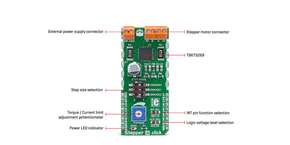
A LOW to HIGH transition (rising edge) on the CLK pin of the TB67S269FTG IC will perform one rotational step. The direction of the rotation is controlled by the logic state on the CW/CCW pin (routed to the mikroBUS™ AN pin, labeled as DIR). The step size is determined by three pins: DMODE0, DMODE1, and DMODE2. It is possible to work with seven movement step sizes, ranging from full step size up to 1/32 step size. These pins are routed to the DIP switch labeled as STEP MODE, allowing step size to be selected by moving each of them according to the truth table below.
The ENABLE pin allows the host MCU to enable or disable the output stages of the TB67S269FTG IC. Asserting this pin to a HIGH logic level enables the output stage. The RESET pin is used to reset the electrical angle to the initial position and it is active HIGH. The ENABLE pin is routed to the CS (labeled as EN), while the RESET pin is routed to the RST pin of the mikroBUS™, allowing the host MCU to control the IC via these pins.
The TB67S269FTG offers monitoring of the electrical angle and fault condition signaling. These two pins are routed to the SMD jumper labeled as INT SEL. While in MO position, the angle monitoring pin will be routed to the mikroBUS™ INT pin. If the jumper is set at LO position, it will route the LO pin to the INT pin of the mikroBUS™, allowing faulty conditions, such as the thermal failure or overcurrent failure, to be reported. Both of these pins feature a pull-up resistor and will have a LOW logic level when asserted.
This Click board™ can be interfaced with both 3.3V and 5V MCUs, thanks to an SMD jumper, labeled as VCC SEL. It is enough to move the SMD jumper to the appropriate position (3V3 or 5V), and the logic voltage level of the communication signals will be properly set for both types of MCUs.
The Click board™ is equipped with the input and output screw terminals. The terminal labeled as TB1 on the schematic is used to connect the external power supply, which should stay in the range from 10V to 35V. The stepper motor can be connected securely via the TB2 and TB3 screw terminals, with their input terminals labeled as A+, A-, and B+, B-.
Type
Stepper
Applications
This Click board™ is a perfect solution for building applications that require precise stepper motor control, such as movement control of beds, heads, and assemblies of various CNC plotting, milling and 3D printer designs, etc.
On-board modules
TB67S269FTG, a bipolar stepper motor driver IC with a translator section, from Toshiba Corporation
Key Features
Integrated translation section used to simplify the control, ability to run in full to 1/32 step, overcurrent and thermal protection, advanced current regulation for consistent torque between steps, user adjustable torque, etc.
Interface
GPIO
Feature
No ClickID
Compatibility
mikroBUS™
Click board size
L (57.15 x 25.4 mm)
Input Voltage
3.3V or 5V
This table shows how the pinout on Stepper 4 click corresponds to the pinout on the mikroBUS™ socket (the latter shown in the two middle columns).
| Notes | Pin | Pin | Notes | ||||
|---|---|---|---|---|---|---|---|
| Direction | DIR | 1 | AN | PWM | 16 | ST |
Step trigger |
| Reset | RST | 2 | RST | INT | 15 | INT | Angle/Error |
| Chip Enable | EN | 3 | CS | RX | 14 | NC | |
| NC | 4 | SCK | TX | 13 | NC | ||
| NC | 5 | MISO | SCL | 12 | NC | ||
| NC | 6 | MOSI | SDA | 11 | NC | ||
| Power supply | +3V | 7 | 3.3V | 5V | 10 | +5V | Power supply |
| Ground | GND | 8 | GND | GND | 9 | GND | Ground |
| Description | Min | Typ | Max | Unit |
|---|---|---|---|---|
| External power supply voltage | 10 | - | 35 | V |
| Current limit (per channel) | - | - | 1.2 | A |
| Step size | 1 | - | 1/32 | step |
| Label | Name | Default | Description |
|---|---|---|---|
| LD1 | PWR | - | Power LED indicator |
| INT SEL | INT SEL | Left | INT pin function selection: left position angle monitoring, right position error reporting. |
| VCC SEL | VCC SEL | Left | Logic voltage level selection: left position 3.3V, right position 5V. |
| SW1 | STEP MODE | Right | Step size selection DIP SW: left position 0, right position 1 (settings in the truth table). |
| TB1 | VIN | - | External power supply connector |
| TB2 | A+, A- | - | Stepper motor coil A connector |
| TB3 | B+, B- | - | Stepper motor coil B connector |
We provide a library for the Stepper 4 Click as well as a demo application (example), developed using MIKROE compilers. The demo can run on all the main MIKROE development boards.
Package can be downloaded/installed directly from NECTO Studio Package Manager (recommended), downloaded from our LibStock™ or found on MIKROE github account.
Library Description
This library contains API for Stepper 4 Click driver.
Key functions
stepper4_set_direction This function sets the motor direction by setting the DIR pin logic state.
stepper4_drive_motor This function drives the motor for the specific number of steps at the selected speed.
stepper4_reset_device This function resets the device by toggling the RST pin.
Example Description
This example demonstrates the use of the Stepper 4 Click by driving the motor in both directions for a desired number of steps.
void application_task ( void )
 {
     log_printf ( &logger, " Move 200 steps clockwise rnn" );
     stepper4_set_direction ( &stepper4, STEPPER4_DIR_CW );
     stepper4_drive_motor ( &stepper4, 200, STEPPER4_SPEED_FAST );
     Delay_ms ( 1000 );
     Delay_ms ( 1000 );

     log_printf ( &logger, " Move 100 steps counter-clockwise rnn" );
     stepper4_set_direction ( &stepper4, STEPPER4_DIR_CCW );
     stepper4_drive_motor ( &stepper4, 100, STEPPER4_SPEED_FAST );
     Delay_ms ( 1000 );
     Delay_ms ( 1000 );
 }
The full application code, and ready to use projects can be installed directly from NECTO Studio Package Manager (recommended), downloaded from our LibStock™ or found on MIKROE github account.
Other MIKROE Libraries used in the example:
Additional notes and informations
Depending on the development board you are using, you may need USB UART click, USB UART 2 Click or RS232 Click to connect to your PC, for development systems with no UART to USB interface available on the board. UART terminal is available in all MIKROE compilers.
This Click board™ is supported with mikroSDK - MIKROE Software Development Kit. To ensure proper operation of mikroSDK compliant Click board™ demo applications, mikroSDK should be downloaded from the LibStock and installed for the compiler you are using.
For more information about mikroSDK, visit the official page.
NOTE: Please be advised that any peripheral devices or accessories shown connected to the Click board™ are not included in the package. Check their availability in our shop or in the YMAN section below.

$889.00

$9.60

$95.00

$549.00

$299.00

$29.00

$23.49

$6.59

$3.60

$119.00

$449.00

$349.00

$349.00

$349.00

$299.00

$269.00

$249.00

$209.00
