Electric motors are the most common way to translate electrical to mechanical energy and because of that they are everywhere around us. Fans, pumps, toys and electrical tools are just some examples. The main classification can be made by type of the power supply. DC motors are usually used where battery power is needed. AC motors are usually used in industry and for appliances where higher power is needed. The power can vary from a few milliwatts to several hundred megawatts. There can be a written tome of pages about this but in this article we will concentrate on a special kind of DC motors called - Stepper motor.

Stepper Motors
Usually when you connect power supply to the any kind of motor, no matter AC or DC, it will start rotation. Some motors allow control of rotation speed by changing the voltage of the power supply. Stepper motors are a kind of motor which allows you to control the amount of rotation and also the rotation speed by sending impulses to inputs or by changing the logic on inputs. For example with stepper motors you can turn the rotor for just 45 degrees in a half of a second, if needed.
Torque of steppers is generally the highest when there is no movement of the rotor and the torque decreases with increase of rotation speed. The current on steppers is highest when there is no movement, so that is opposite to the other types of DC motors. That is the reason they tend to run hot.
Steppers are found in places where high precision is needed. For example they are used inside floppy disk drives and CD players for head movement. They are an indispensable part of CNC machines. Printers uses steppers too.
There are three main types of stepper motors :
- Permanent magnet stepper
- Hybrid synchronous stepper
- Variable reluctance stepper
Permanent magnet motors use a permanent magnet in the rotor and operate on the attraction or repulsion between the rotor and the stator electromagnets. Variable reluctance motors have a plain iron rotor and operate based on the principle that minimum reluctance occurs with minimum gap, hence the rotor points are attracted toward the stator magnet poles.
How A Stepper Works
An illustration might be the easiest way to explain how stepper motor works.
First, we have diagrams of steppers with stator which have 4 coils. Every coil has its' own inputs so we have to have 8 input wires. Keep in mind that negative ( GND ) wire is common for all coils which in reality means that we have 5 input wires. Coils on stator are marked with A, B, C and D. By switching the power on coils in the same order as their position on the stator, we can turn the rotor by one full circle in four steps. This is sometimes called "full step" driving of the motor.
Next is half-step driving of stepper motor. Now we need 8 steps to make a full circle. If we add the gearing to something like this we can make a motor with an exact number of steps per full circle. Keep in mind that high gear ratio at the rotor also adds torque to the output. The disadvantage of the high gear ratio is lower maximum speed at output.
The number of steps per revolution usually varies between 4 and 400. The most common values are 200 and 48; depending on where the motor will be used, you can choose stepper with the exact number of steps per revolution.
There are also bipolar stepper motors which are a little more complex to drive than unipolar motors.
There is also 4 coils, like in the case of unipolar. In this case when C and A coil are charged, their polarities are opposite to each other, and the same with D and B coils. This means that we only have 4 input wires.
Microsteps
The half-step is a specific form of microstepping. There are other variations because you are not limited to turning the coils fully on or off. You could feed 1/4 power to A and 3/4 power to B, and get a position that is closer to B than A. This technique can bring smoother rotation but the biggest disadvantage is probably very low speed.
Even More Coils
If you have ever opened or seen what is inside a stepper motor you probably realized that there is more than 4 coils around the rotor. That is OK, but why then does your motor still have 5 wires? One for common ground and four wires for every single coil?

Every coil connected to the same circuit is one phase. This diagram represents the 4 phases stepper motor with two coils per phase and 8 steps per revolution for full step drive or 16 steps for half step drive. Same technique can be used for bipolar steppers.
Unipolar or Bipolar
Both types have their own advantages. In reality bipolar motors produce even more torque on output - about 40% more than unipolar. A disadvantage is the electronics required to drive each circuit, because they must change polarity as well as turning on and off. This is often accomplished using a circuit called an H-bridge. Bipolar types also require fewer wingdings which means that you can get a smaller motor with the same torque power as unipolar.
Summary
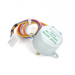
Stepper motors have many variations. The price can vary from a few euros per piece to several hundred euros for some really big and strong motors which can be used for professional CNC machines. The choice strongly depends on the type of application. MikroElektronika offers small and cheap 4 phase unipolar steppers, excellent for education. You will feel no sorrow if you burn it out, so feel free and explore.


