


OFF
GO LOCAL
| Company | Stock | Price |
|---|---|---|


MIKROE-6707
22 g
Status:
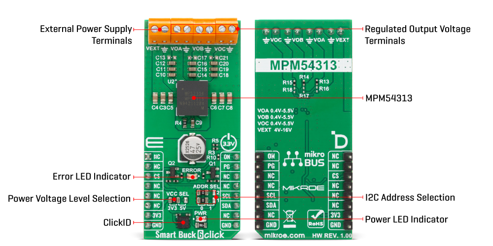
Smart Buck 6 Click is a compact add-on board that provides a multi-rail power management solution designed to supply embedded systems with stable and configurable power outputs. It is based on the MPM54313, a triple 3A power module from MPS, which integrates three independent buck converters, each capable of delivering up to 3A of output current. The module supports a wide 4V to 16V input range, with output voltages adjustable from 0.4V to 5.5V through the I2C interface or multiple-time programmable memory. It incorporates advanced features such as power-on/off sequencing, configurable soft-start, constant-on-time control for ultra-fast transient response, active voltage positioning, and the ability to parallel channels for higher current demands up to 6A. The Smart Buck 6 Click is ideally suited for powering FPGAs, ASICs, networking equipment, telecommunications devices, and optical communication modules.
Smart Buck 6 Click is fully compatible with the mikroBUS™ socket and can be used on any host system supporting the mikroBUS™ standard. It comes with the mikroSDK open-source libraries, offering unparalleled flexibility for evaluation and customization. What sets this Click board™ apart is the groundbreaking ClickID feature, enabling your host system to automatically detect and identify this add-on board.
This product is no longer in stock
Availability date:
OFF
| Company | Stock | Price |
|---|---|---|
Smart Buck 6 Click is based on the MPM54313, a triple 3A power module from MPS that provides a highly integrated power management solution for a wide range of embedded applications. This module offers three independent buck converters, each capable of delivering up to 3A of continuous output current, with flexible configuration through the I2C interface. It supports a wide input voltage range from 4V to 16V at the VEXT terminal, while the output voltages can be adjusted digitally via I2C or set through multiple-time programmable memory in the range of 0.4V to 5.5V on all VOx outputs, ensuring adaptability to different system requirements.
The device integrates sophisticated power-on and power-off sequencing, configurable soft-start, compensation, and comprehensive protection features including under-voltage lockout, over-voltage, under-voltage, over-current protection, and thermal shutdown, ensuring safe and reliable operation. Its constant-on-time control architecture enables ultra-fast transient response, making it ideal for powering sensitive digital systems such as FPGAs, ASICs, and optical communication modules.
For higher current demands, Buck channels A and B can operate in parallel in interleaving mode, supporting up to 6A with active current balancing, while configurable active voltage positioning allows up to three outputs to be paralleled with passive current sharing. This level of integration and flexibility makes Smart Buck 6 Click an excellent choice for networking, telecommunications, and other complex embedded systems requiring compact and programmable multi-rail power supplies.
The MPM54313 interfaces with the host MCU via an I2C-compatible serial interface operating at standard (100kHz) or fast mode (400kHz) clock speeds, enabling control and monitoring of output voltages and status registers. The I2C address of the MPM54313 can be easily configured via onboard jumpers marked ADDR SEL, allowing multiple devices to coexist on the same bus.
A dedicated ON pin allows for external enable/disable control of the entire power module, supporting power domain management in software-controlled power sequencing scenarios. Additionally, the MPM54313 features a Power Good (PG pin) output that is also routed to an onboard red LED labeled ERROR, which provides real-time visual indication of any voltage irregularities or faults - indicate valid and stable output voltages.
This Click board™ can operate with either 3.3V or 5V logic voltage levels selected via the VCC SEL jumper. This way, both 3.3V and 5V capable MCUs can use the communication lines properly. Also, this Click board™ comes equipped with a library containing easy-to-use functions and an example code that can be used as a reference for further development.
Type
Buck
Applications
Ideal for powering FPGAs, ASICs, networking equipment, telecommunications devices, and optical communication modules
On-board modules
MPM54313 - triple 3A power module from MPS
Key Features
Three independent buck converters, adjustable output voltage via I2C interface or MTP memory, power-on and power-off sequencing, configurable soft-start, constant-on-time control for ultra-fast transient response, active voltage positioning with passive current sharing, parallel operation of buck channels up to 6A with interleaving mode and active current balancing, protection, Power Good output, and more
Interface
I2C
Feature
ClickID
Compatibility
mikroBUS™
Click board size
L (57.15 x 25.4 mm)
Input Voltage
3.3V,External
This table shows how the pinout on Smart Buck 6 Click corresponds to the pinout on the mikroBUS™ socket (the latter shown in the two middle columns).
| Notes | Pin | Pin | Notes | ||||
|---|---|---|---|---|---|---|---|
| NC | 1 | AN | PWM | 16 | ON | Device Enable | |
| NC | 2 | RST | INT | 15 | PG | Power-Good Indicator | |
| ID COMM | CS | 3 | CS | RX | 14 | NC | |
| NC | 4 | SCK | TX | 13 | NC | ||
| NC | 5 | MISO | SCL | 12 | SCL | I2C Clock | |
| NC | 6 | MOSI | SDA | 11 | SDA | I2C Data | |
| Power Supply | 3.3V | 7 | 3.3V | 5V | 10 | NC | |
| Ground | GND | 8 | GND | GND | 9 | GND | Ground |
| Label | Name | Default | Description |
|---|---|---|---|
| LD1 | PWR | - | Power LED Indicator |
| LD3 | ERROR | - | Error LED Indicator |
| JP1 | VCC SEL | Left | Power Voltage Level Selection 3V3/5V: Left position 3V3, Right position 5V |
| JP2-JP3 | ADDR SEL | Left | I2C Address Selection 0/1: Left position 0, Right position 1 |
| Description | Min | Typ | Max | Unit |
|---|---|---|---|---|
| Supply Voltage | 3.3 | - | 5 | V |
| External Power Supply | 4 | - | 16 | V |
| Output Voltage | 0.4 | - | 5.5 | V |
| Output Current | - | - | 3 | A |
Smart Buck 6 Click demo application is developed using the NECTO Studio, ensuring compatibility with mikroSDK's open-source libraries and tools. Designed for plug-and-play implementation and testing, the demo is fully compatible with all development, starter, and mikromedia boards featuring a mikroBUS™ socket.
Example Description
This example demonstrates the use of the Smart Buck 6 Click board. The application changes the output voltage of all three buck converters (A, B, and C) in a periodic manner and logs the output current of each. It also monitors the PG (Power Good) pin to detect and log any fault conditions such as over-temperature, overvoltage, undervoltage, or overcurrent.
Key Functions
smartbuck6_cfg_setup This function initializes Click configuration structure to initial values.smartbuck6_init This function initializes all necessary pins and peripherals used for this Click board.smartbuck6_default_cfg This function executes a default configuration of Smart Buck 6 Click board.smartbuck6_set_buck_vout This function sets the output voltage for one or more buck regulators.smartbuck6_read_buck_current This function reads and returns the output current of the selected buck regulator.smartbuck6_get_pg_pin This function reads the logic level of the PG pin.Application Init
Initializes the logger and the Smart Buck 6 Click driver and applies the default configuration.
Application Task
Periodically increases or decreases the output voltage, reads and logs the output current for each buck channel, and checks for any fault conditions indicated via the PG pin and status registers.
Application Output
This Click board can be interfaced and monitored in two ways:
Additional Notes and Information
The complete application code and a ready-to-use project are available through the NECTO Studio Package Manager for direct installation in the NECTO Studio. The application code can also be found on the MIKROE GitHub account.
NOTE: Please be advised that any peripheral devices or accessories shown connected to the Click board™ are not included in the package. Check their availability in our shop or in the YMAN section below.

$889.00

$95.00

$549.00

$299.00

$29.00

$29.00

$6.59

$3.60

$119.00

$349.00

$349.00

$349.00

$299.00

$449.00

$269.00

$249.00

$209.00
