


OFF
GO LOCAL
| Company | Stock | Price |
|---|---|---|


MIKROE-5750
23 g
Status:
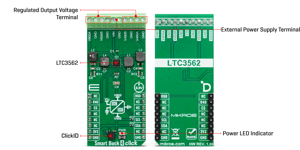
Smart Buck 4 Click is a compact add-on board that contains a high-frequency synchronous step-down DC-DC converter. This board features the LTS3562, a quad synchronous step-down DC-DC regulator from Analog Devices. It uses voltages in the range of 2.85V up to 5.5V as input. As output, the converter can scale voltage from 425mV up to 3.755V in 25mV steps, retaining up to 600mA of output current, operating at 2.5MHz of the typical switching frequency. This Click board™ makes the perfect solution for the development of DSPs power supplies, portable devices, dynamic voltage scaling, and more.
Smart Buck 4 Click is fully compatible with the mikroBUS™ socket and can be used on any host system supporting the mikroBUS™ standard. It comes with the mikroSDK open-source libraries, offering unparalleled flexibility for evaluation and customization. What sets this Click board™ apart is the groundbreaking ClickID feature, enabling your host system to seamlessly and automatically detect and identify this add-on board.
This product is no longer in stock
Availability date:
OFF
| Company | Stock | Price |
|---|---|---|
Smart Buck 4 Click is based on the LTS3562, a quad synchronous step-down DC-DC regulator from Analog Devices. The LTS3562 has four independent I2C controllable step-down regulators, two of them with an output current of up to 600mA and two with an output current of up to 400mA. The Type A regulators are externally adjustable and have a programmable feedback voltage of 425mV up to 800mV (R600A, R400A) in 25mV steps. The Type B regulators have a fixed output, and their output voltages can be programmed between 600mV and 3.755V (R600B, R400B) in 25mV steps. The R600A regulator has a Power-on-reset output feature. Both Type A and Type B have separate RUN pins that can be enabled if I2C control is unavailable.
The LTS3562 has several programmable modes in which all four regulators can operate. In Pulse skip mode, an internal latch is set at the start of every 2.25MHz cycle, which turns the main P-channel MOSFET on. In LDO mode, the switching regulators are converted to linear regulators, thus delivering continuous power. This mode gives the LTS3562 a DC option and the lowest possible output noise. In Burst mode, the switching regulator automatically switches between the hysterical control and a fixed-frequency pulse skip operation. The first is automatically switched at light loads, while the latter is switched at heavy loads. In Forced Burst mode, the switching regulators use a constant-current algorithm to control the inductor current, and in this mode, the output power is limited.
The Smart Buck 4 Click uses a standard 2-Wire I2C interface to communicate with the host MCU supporting speeds up to 400KHz. The LTS3562 is a receive-only device, and the I2C address is fixed and can not be changed. As mentioned above, you can manage both Type A and Type B regulators with active LOW by a host MCU over the R40 and R60 pins.
This Click board™ can be operated only with a 3.3V logic voltage level. The board must perform appropriate logic voltage level conversion before using MCUs with different logic levels. However, the Click board™ comes equipped with a library containing functions and an example code that can be used, as a reference, for further development.
Type
Buck
Applications
Can be used for the development of DSPs power supplies, portable devices, dynamic voltage scaling, and more
On-board modules
LTS3562 - quad synchronous step-down DC-DC regulator from Analog Devices
Key Features
Highest efficiency, excellent DC output voltage, four independently programmable regulators, two of them with programmable feedback voltage, two with programmable output voltage, fixed switching frequency in pulse skip mode, power-on-reset output, and more
Interface
I2C
Feature
ClickID
Compatibility
mikroBUS™
Click board size
L (57.15 x 25.4 mm)
Input Voltage
3.3V,External
This table shows how the pinout on Smart Buck 4 Click corresponds to the pinout on the mikroBUS™ socket (the latter shown in the two middle columns).
| Notes | Pin | Pin | Notes | ||||
|---|---|---|---|---|---|---|---|
| NC | 1 | AN | PWM | 16 | R60 | R600 Output Enable | |
| R400 Output Enable | R40 | 2 | RST | INT | 15 | NC | |
| ID COMM | CS | 3 | CS | RX | 14 | NC | |
| NC | 4 | SCK | TX | 13 | NC | ||
| NC | 5 | MISO | SCL | 12 | SCL | I2C Clock | |
| NC | 6 | MOSI | SDA | 11 | SDA | I2C Data | |
| Power Supply | 3.3V | 7 | 3.3V | 5V | 10 | NC | |
| Ground | GND | 8 | GND | GND | 9 | GND | Ground |
| Label | Name | Default | Description |
|---|---|---|---|
| LD1 | PWR | - | Power LED Indicator |
| Description | Min | Typ | Max | Unit |
|---|---|---|---|---|
| Supply Voltage | - | 3.3 | - | V |
| External Voltage Range | 2.85 | - | 5.5 | V |
| Output Voltage Range | 425 | - | 3775 | mV |
| Output Current R400/R600 | - | - | 400/600 | mA |
We provide a library for the Smart Buck 4 Click as well as a demo application (example), developed using MikroElektronika compilers. The demo can run on all the main MikroElektronika development boards.
Package can be downloaded/installed directly from NECTO Studio Package Manager (recommended), downloaded from our LibStock™ or found on Mikroe github account.
Library Description
This library contains API for Smart Buck 4 Click driver.
Key functions
smartbuck4_en_r40_reg Smart Buck 4 enable 400A regulator function.
smartbuck4_send_command Smart Buck 4 send command function.
smartbuck4_disable_regulators Smart Buck 4 disable regulators function.
Example Description
This example demonstrates the use of the Smart Buck 4 Click board. This driver provides functions for device configurations and for the setting of the output voltage.
 void application_task ( void )
 {
     for ( uint8_t n_cnt = SMARTBUCK4_REGULATOR_B_600_MV;
           n_cnt <= SMARTBUCK4_REGULATOR_B_3700_MV;
           n_cnt += SMARTBUCK4_REGULATOR_B_700_MV )
     {
         err_t error_flag = smartbuck4_send_command( &smartbuck4, SMARTBUCK4_REG_R600B_PROGRAM |
                                                                  SMARTBUCK4_REG_R400B_PROGRAM |
                                                                  SMARTBUCK4_REG_LDO_MODE,
                                                                  SMARTBUCK4_ENABLE_REGULATOR | n_cnt );
         if ( SMARTBUCK4_OK == error_flag )
         {
             log_printf( &logger, " Set output to %d mV. rn",
                         ( SMARTBUCK4_MIN_VOLTAGE + n_cnt * SMARTBUCK4_STEP ) );
         }
         else
         {
             log_error( &logger, " Transmission error occurred." );
             smartbuck4_disable_regulators( &smartbuck4 );
             for ( ; ; );
         }
         Delay_ms( 5000 );
     }
 }
The full application code, and ready to use projects can be installed directly from NECTO Studio Package Manager (recommended), downloaded from our LibStock™ or found on Mikroe github account.
Other Mikroe Libraries used in the example:
Additional notes and informations
Depending on the development board you are using, you may need USB UART click, USB UART 2 Click or RS232 Click to connect to your PC, for development systems with no UART to USB interface available on the board. UART terminal is available in all MikroElektronika compilers.
This Click board™ is supported with mikroSDK - MikroElektronika Software Development Kit. To ensure proper operation of mikroSDK compliant Click board™ demo applications, mikroSDK should be downloaded from the LibStock and installed for the compiler you are using.
For more information about mikroSDK, visit the official page.
NOTE: Please be advised that any peripheral devices or accessories shown connected to the Click board™ are not included in the package. Check their availability in our shop or in the YMAN section below.

$889.00

$95.00

$549.00

$299.00

$29.00

$29.00

$3.30

$3.60

$119.00

$449.00

$349.00

$349.00

$349.00

$299.00

$269.00

$249.00

$209.00
