


OFF
GO LOCAL
| Company | Stock | Price |
|---|---|---|


MIKROE-6470
20 g
Status:
ML Vibro Sens Click is a compact add-on board for motion sensing and vibration analysis. This board features the FXLS8974CF, a 3-axis low-g 12-bit digital accelerometer from NXP designed for precise motion detection and data collection. This Click board™ represents a machine learning training tool that communicates with the host MCU over an I2C interface, with selectable addresses and dual operating modes for interrupt signaling or motion detection. It features two DC motors - a balanced motor for generating steady baseline vibrations and an unbalanced motor for customizable vibration patterns controlled via PWM or PDM signals. Ideal for industrial diagnostics, IoT systems, wearable devices, and environmental monitoring, ML Vibro Sens Click provides reliable motion data for training ML algorithms in diverse applications.
ML Vibro Sens Click is fully compatible with the mikroBUS™ socket and can be used on any host system supporting the mikroBUS™ standard. It comes with the mikroSDK open-source libraries, offering unparalleled flexibility for evaluation and customization. What sets this Click board™ apart is the groundbreaking ClickID feature, enabling your host system to seamlessly and automatically detect and identify this add-on board.
This product is no longer in stock
Availability date:
OFF
| Company | Stock | Price |
|---|---|---|
ML Vibro Sens Click is a machine learning training tool based on the FXLS8974CF, a 3-axis low-g 12-bit digital accelerometer from NXP. Designed for applications requiring precise motion sensing, this Click board™ is an excellent choice for testing and training ML algorithms in both industrial and IoT environments. The FXLS8974CF offers the versatility of ultra-low-power operation alongside high-performance modes, ensuring efficient use in diverse scenarios. Its integrated digital features simplify data collection and reduce system power consumption, while its robust performance over extended temperature ranges enhances reliability in demanding applications, including industrial diagnostics, wearable technology, and environmental monitoring.
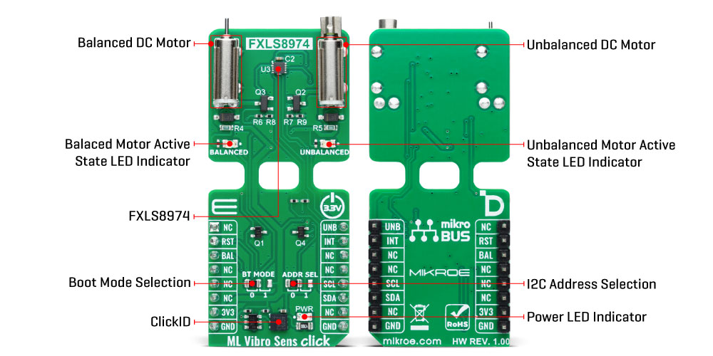
This Click board™ incorporates two DC motors to simulate vibration stimuli for machine learning: a balanced and an unbalanced motor. The BALANCED motor generates steady "nominal" vibrations, serving as a baseline signal for training ML models in a "healthy" state. On the other hand, the UNBALANCED motor is designed to provide customizable vibration signals, ranging from low-intensity to specific frequency-based vibrations. This motor is powered via the UNB signal, which supports PWM or PDM inputs, allowing precise modulation of vibration characteristics. Applying a continuous power signal to the unbalanced motor is not recommended due to its intensity, so a low-frequency, low-duty-cycle PWM signal is suggested for controlled vibration stimuli.
The BAL signal powers the balanced motor, maintaining a stable vibration environment for baseline training. Both motors are used from the IND-YZ0412J series, known for their high-frequency vibration capabilities. The board features orange LED indicators labeled BALANCED and UNBALANCED to visually indicate motor activity, which lights up when their respective motors are active.
The FXLS8974CF accelerometer is essential for ML Vibro Sens Click as it provides precise motion and vibration measurement across three axes (X, Y, Z), forming the foundation for training machine learning algorithms. It captures detailed data from the balanced and unbalanced motors, enabling the differentiation between "healthy" baseline states and anomalous conditions. With its customizable sensitivity, it supports high-performance and low-power modes, ensuring flexibility for various application needs.
The FXLS8974CF communicates with the host MCU via a standard 2-wire I2C interface, supporting clock frequencies up to 1MHz. Its I2C address can be configured through the onboard ADDR SEL jumper, offering flexibility in multi-sensor setups. Additional BT MODE jumper allows users to enable users to select between two distinct operating modes, tailoring the board's functionality. In addition to the interface pins, the board uses the INT pin, whose behavior is determined by the setting of the BT MODE jumper.
In Default Mode (position 0), the INT pin acts as a programmable interrupt output, allowing the accelerometer to signal specific events - such as motion detection or threshold breaches - directly to the host MCU. Conversely, in Motion Detection Mode (position 1), the INT pin functions as a multifunction I/O, enabling the host MCU to configure motion detection thresholds or activate custom responses triggered by detected motion.
This Click board™ can be operated only with a 3.3V logic voltage level. The board must perform appropriate logic voltage level conversion before using MCUs with different logic levels. Also, it comes equipped with a library containing functions and an example code that can be used as a reference for further development.
Type
Motion,Vibration
Applications
Ideal for industrial diagnostics, IoT systems, wearable devices, and environmental monitoring for training ML algorithms in diverse applications
On-board modules
FXLS8974CF - 3-axis low-g 12-bit digital accelerometer from NXP
Key Features
Dual DC motors for customizable vibration signals, PWM support for precise vibration modulation, I2C interface with adjustable address, selectable boot mode, programmable interrupt, visual feedback on motor activity, and more
Interface
GPIO,I2C
Feature
ClickID
Compatibility
mikroBUS™
Click board size
L (57.15 x 25.4 mm)
Input Voltage
3.3V
This table shows how the pinout on ML Vibro Sens Click corresponds to the pinout on the mikroBUS™ socket (the latter shown in the two middle columns).
| Notes | Pin | Pin | Notes | ||||
|---|---|---|---|---|---|---|---|
| NC | 1 | AN | PWM | 16 | UNB | Unbalanced Motor Control | |
| ID SEL | RST | 2 | RST | INT | 15 | INT | Interrupt |
| Balanced Motor Control / ID COMM | BAL | 3 | CS | RX | 14 | NC | |
| NC | 4 | SCK | TX | 13 | NC | ||
| NC | 5 | MISO | SCL | 12 | SCL | I2C Clock | |
| NC | 6 | MOSI | SDA | 11 | SDA | I2C Data | |
| Power Supply | 3.3V | 7 | 3.3V | 5V | 10 | NC | |
| Ground | GND | 8 | GND | GND | 9 | GND | Ground |
| Label | Name | Default | Description |
|---|---|---|---|
| LD1 | PWR | - | Power LED Indicator |
| LD2 | BALANCED | - | Balanced Motor Active State LED Indicator |
| LD3 | UNBALANCED | - | Unbalanced Motor Active State LED Indicator |
| JP5 | BT MODE | Left | Boot Mode Selection 0/1: Left position 0, Right position 1 |
| JP6 | ADDR SEL | Left | I2C Address Selection 0/1: Left position 0, Right position 1 |
| Description | Min | Typ | Max | Unit |
|---|---|---|---|---|
| Supply Voltage | - | 3.3 | - | V |
| Accel Full-Scale Measurement Range | ±2 | - | ±16 | g |
| Accel Sensitivity | 0.98 | - | 7.81 | mg/LSB |
We provide a library for the ML Vibro Sens Click as well as a demo application (example), developed using MIKROE compilers. The demo can run on all the main MIKROE development boards.
Package can be downloaded/installed directly from NECTO Studio Package Manager (recommended), downloaded from our LibStock™ or found on MIKROE github account.
Library Description
This library contains API for ML Vibro Sens Click driver.
Key functions
mlvibrosens_get_int_pin This function returns the interrupt pin logic state.
mlvibrosens_get_data This function reads accel X, Y, and Z axis data in g and temperature in degrees Celsius.
mlvibrosens_set_vibro_state This function sets the vibro motors state.
Example Description
This example demonstrates the use of the ML Vibro Sens Click by capturing and logging acceleration data on the X, Y, and Z axes, along with temperature readings. The data is output
over USB UART and can be visualized in real-time using tools like SerialPlot. Additionally,
the vibro motor state changes periodically, cycling through different vibration states for
added feedback.
void application_task ( void )
 {
     static uint8_t vibro_state = MLVIBROSENS_VIBRO_STATE_IDLE;
     static uint16_t result_num = 0;
     static mlvibrosens_data_t accel_data;

     // Wait for a data ready interrupt
     while ( mlvibrosens_get_int_pin ( &mlvibrosens ) );

     if ( MLVIBROSENS_OK == mlvibrosens_get_data ( &mlvibrosens, &accel_data ) )
     {
         log_printf ( &logger, "%f;%f;%f;%d;rn", accel_data.x, accel_data.y,
                                                   accel_data.z, accel_data.temperature );
     }
     if ( ++result_num > 1000 )
     {
         result_num = 0;
         if ( ++vibro_state > MLVIBROSENS_VIBRO_STATE_BOTH )
         {
             vibro_state = MLVIBROSENS_VIBRO_STATE_IDLE;
         }
         mlvibrosens_set_vibro_state ( &mlvibrosens, vibro_state );
     }
 }
The full application code, and ready to use projects can be installed directly from NECTO Studio Package Manager (recommended), downloaded from our LibStock™ or found on MIKROE github account.
Other MIKROE Libraries used in the example:
Additional notes and informations
Depending on the development board you are using, you may need USB UART Click, USB UART 2 Click or RS232 Click to connect to your PC, for development systems with no UART to USB interface available on the board. UART terminal is available in all MIKROE compilers.
This Click board™ is supported with mikroSDK - MIKROE Software Development Kit. To ensure proper operation of mikroSDK compliant Click board™ demo applications, mikroSDK should be downloaded from the LibStock and installed for the compiler you are using.
For more information about mikroSDK, visit the official page.
NOTE: Please be advised that any peripheral devices or accessories shown connected to the Click board™ are not included in the package. Check their availability in our shop or in the YMAN section below.

$889.00

$95.00

$549.00

$299.00

$29.00

$29.00

$6.59

$3.60

$119.00

$449.00

$349.00

$349.00

$349.00

$299.00

$269.00

$249.00

$209.00
