


OFF
LightRanger 7 Click
GO LOCAL
| Company | Stock | Price |
|---|---|---|


21 g
Status:
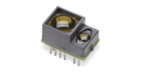
LightRanger 7 Click is a compact add-on board capable of precise distance measurement and motion tracking. This board features the AFBR-S50, a medium-range 3D multipixel Time-of-Flight (ToF) sensor from Broadcom. Besides a VCSEL-based ToF sensor (Laser Class 1 eye safety), optimized to measure various distances working equally well on white, black, colored, and metallic reflective surfaces, this board also includes a 32-bit MCU, RA4M2 group of Renesas MCU with Arm® Cortex®-M33 core, alongside a 4-pin standard CAN connections compatible with Pixhawk®, a popular general-purpose flight controller. This Click board™ makes the perfect solution for robotics and industrial applications requiring precise 3D information and an extended range like drones or AMR/AGV.
LightRanger 7 Click is fully compatible with the mikroBUS™ socket and can be used on any host system supporting the mikroBUS™ standard. It comes with the mikroSDK open-source libraries, offering unparalleled flexibility for evaluation and customization. What sets this Click board™ apart is the groundbreaking ClickID feature, enabling your host system to seamlessly and automatically detect and identify this add-on board.
NOTE: This Click board™ can also be found in a customized version for all AFBR-S50 sensors, which can be used as a complete ToF solution in an out-of-the-box manner, cutting the time to market. For more information, please visit the AFBR-S50 ToF Sensor Board product page.
NOTE: The LightRanger 7 - Socket version comes only with a socket specifically designed for the AFBR-S50 sensors but does not include the AFBR-S50 sensor itself.
This product is no longer in stock
Availability date: 09/05/2023
OFF
| Company | Stock | Price |
|---|---|---|
LightRanger 7 Click is based on the AFBR-S50, a multi-pixel optical distance and motion measurement sensor module based on the Time-of-Flight principle from Broadcom. The AFBR-S50 is developed with a particular focus on applications with the need for the highest speed and accuracy at medium distance ranges with low power consumption. Due to its best-in-class ambient light suppression, use in outside environments is possible in direct sunlight and on white, black, colored, metallic, and retroreflective surfaces. This feature makes it suitable for optical distance measurements requiring precise 3D information and extended range like drones or AMR/AGV.

This board represents an integrated solution consisting of a 32-bit MCU, RA4M2 group of Renesas MCU with Arm® Cortex®-M33 core, and a ToF sensor with an integrated infrared laser light source mounted on a compact-sized PCB. In addition to an SPI-compatible interface for data transferring to the RA4M2 MCU, the AFBR-S50 also has an interrupt line through which the MCU can register the data-ready event. Also, such conditions and other interrupts can be visually represented using the yellow LED indicator marked with STATUS. The RA4M2 interfaces with a host MCU through UART communication via commonly used RX and TX mikorBUS™ pins.
Since the AFBR-S50 is known to be used in both robotics and drones, it is essential to note that this ToF sensor is compatible with Pixhawk®, a popular general-purpose flight controller, accessible via two 4-pin CAN connectors, J1 and J2, and controllable through onboard CAN controller, the MCP2542WFD from Microchip. Also, there is a clear visual indication of the execution of the communication itself; more precisely, the user can catch the operation of CAN communication/signal transfer via orange LED indicators provided for indication of received and transmitted CAN signals.
In addition, this board also offers complete debugging and programming capabilities supported through an additional header marked with J3. With this header, the user can use a Serial Wire Debug interface for programming and debugging, available through the SWD interface pins. Besides, it also has a Micro B USB connector, allowing the board to be powered and configured by a personal computer (PC). This way, it is possible to flash the AFBR-S50 ToF sensor via bootloader simply.
NOTE: Unlike the BDC-AFBR-S50 TOF Sensor board, which works with the corresponding code that supports USB and CAN communication, this Click board™ comes with a code version that supports USB and UART communication as default, while CAN communication is left as an option for the user. Thanks to the mentioned bootloader, the user can upgrade/degrade the example code and use the code version of the BDC-AFBR-S50 TOF Sensor board on the Click board™.
This Click board™ uses both mikroBUS™ power rails, 3.3V, and 5V. 5V is necessary to power the ToF sensor, while all unnecessary communication and data transfer is done using 3.3V logic. Thanks to the onboard LDO regulator, the SPX3819, even in the standalone CAN configuration, both voltages are provided: 5V through the CAN connector, while the regulator creates a voltage of 3.3V essential for the proper operation of the MCU. Also, this Click board™ comes equipped with a library containing easy-to-use functions and an example code that can be used as a reference for further development.
Procedure:
For further information on the Explorer check out the Getting Started Guide.
Type
Optical
Applications
Can be used for robotics and industrial applications requiring precise 3D information and an extended range like drones or AMR/AGV, human machine interface, automation and control, and more
On-board modules
AFBR-S50 - Time-of-Flight sensor module for distance and motion measurement from Broadcom
Key Features
High speed and accuracy at medium distance ranges with low power consumption, best-in-class ambient light suppression, multipixel for 3D motion detection, Laser Class 1 eye safe ready, compatible with Pixhawk® general-purpose flight controller, various communication interfaces, full debugging and programming capabilities, and more
Interface
CAN,UART,USB
Feature
ClickID
Compatibility
mikroBUS™
Click board size
L (57.15 x 25.4 mm)
Input Voltage
3.3V,5V,5V (via USB)
This table shows how the pinout on LightRanger 7 Click corresponds to the pinout on the mikroBUS™ socket (the latter shown in the two middle columns).
| Notes | Pin | Pin | Notes | ||||
|---|---|---|---|---|---|---|---|
| NC | 1 | AN | PWM | 16 | NC | ||
| Reset | RST | 2 | RST | INT | 15 | NC | |
| ID COMM | CS | 3 | CS | RX | 14 | TX | UART TX |
| NC | 4 | SCK | TX | 13 | RX | UART RX | |
| NC | 5 | MISO | SCL | 12 | NC | ||
| NC | 6 | MOSI | SDA | 11 | NC | ||
| Power Supply | 3.3V | 7 | 3.3V | 5V | 10 | 5V | Power Supply |
| Ground | GND | 8 | GND | GND | 9 | GND | Ground |
| Label | Name | Default | Description |
|---|---|---|---|
| LD1 | PWR | - | Power LED Indicator |
| LD2 | CAN TX | - | CAN Transmitted Signal LED Indicator |
| LD3 | CAN RX | - | CAN Received Signal LED Indicator |
| LD4 | STATUS | - | Status LED Indicator |
| L1-L2 | CAN | Populated | Standardized Pixhawk® CAN Connectors |
| J3 | J3 | Populated | SWD Interface Debug Connector |
 |
|
|
|
|
|
|---|---|---|---|---|---|
| TOF Sensor: | S50MV85I | S50MV85G | S50LV85D | S50LX85D | S50MV68B |
| MIKROE PID | MIKROE-5824 | MIKROE-5680 | MIKROE-5841 | MIKROE-5877 | MIKROE-5840 |
| Typ. Range | 5 m | 10 m | 30 m | 50 m | 10 m |
| Range white @1klx | 12 m | 36 m | 61 m | 78 m | 36 m |
| Range white @100klx | 4 m | 12 m | 20 m | 30 m | 15 m (50klx) |
| Laser Light Source | 850 nm (IR) | 850 nm (IR) | 850 nm (IR) | 850 nm (IR) | 680 nm (red) |
| Illuminated Pixels | 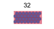 |
 |
 |
|
.png) |
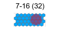
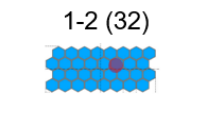
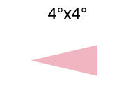
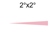
| Usable Sensor FoV | 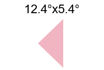 |
 |
 |
|
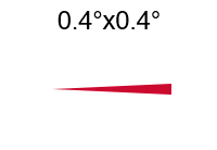 |
| Beam spot size 1m | 23cm x 10cm | 7 cm | 3.5 cm | 3.5 cm | 0.7 cm |
| Typ. Application | AMR/AGV, Factory Automation | Factory Automation, Fill Level | UAV, factory automation, Fill Level | UAV | Factory Automation |
| Description | Min | Typ | Max | Unit |
|---|---|---|---|---|
| External Power Supply Voltage | 3.3 | - | 5 | V |
| Measurement Range | 10 | 3.000 | 6.000 | mm |
| Emission Wavelength | - | 850 | - | nm |
| Ambient Light Illuminance Suppression | - | 100 | 200 | klx |
| Accuracy | - | ±1.5 | - | % |
| Distance Resolution | - | 0.1 | - | mm |
| Precision | 0.5 | 5 | - | mm |
| Description | Min | Typ | Max | Unit |
|---|---|---|---|---|
| External Power Supply Voltage | 3.3 | - | 5 | V |
| Measurement Range | 10 | - | 6.000 | mm |
| Emission Wavelength | - | 850 | - | nm |
| Ambient Light Illuminance Suppression | - | 100 | 200 | klx |
| Accuracy | - | ±1.5 | - | % |
| Distance Resolution | - | 0.1 | - | mm |
| Precision | 0.5 | 5 | - | mm |
| Description | Min | Typ | Max | Unit |
|---|---|---|---|---|
| External Power Supply Voltage | 3.3 | - | 5 | V |
| Measurement Range | 10 | - | 10.000 | mm |
| Emission Wavelength | - | 680 | - | nm |
| Ambient Light Illuminance Suppression | - | 50 | 100 | klx |
| Accuracy | - | ±1.5 | - | % |
| Distance Resolution | - | 0.1 | - | mm |
| Precision | 0.5 | 10 | - | mm |
| Description | Min | Typ | Max | Unit |
|---|---|---|---|---|
| External Power Supply Voltage | 3.3 | - | 5 | V |
| Measurement Range | 10 | - | 10.000 | mm |
| Emission Wavelength | - | 850 | - | nm |
| Ambient Light Illuminance Suppression | - | 100 | 200 | klx |
| Accuracy | - | ±1.5 | - | % |
| Distance Resolution | - | 0.1 | - | mm |
| Precision | 0.5 | 10 | - | mm |
| Description | Min | Typ | Max | Unit |
|---|---|---|---|---|
| External Power Supply Voltage | 3.3 | - | 5 | V |
| Measurement Range | 50 | - | 50.000 | mm |
| Emission Wavelength | - | 850 | - | nm |
| Ambient Light Illuminance Suppression | - | 100 | 200 | klx |
| Accuracy | - | ±2 | - | % |
| Distance Resolution | - | 0.1 | - | mm |
| Precision | 0.5 | 10 | - | mm |
We provide a library for the LightRanger 7 Click as well as a demo application (example), developed using MIKROE compilers. The demo can run on all the main MIKROE development boards.
Package can be downloaded/installed directly from NECTO Studio Package Manager(recommended way), downloaded from our LibStock™ or found on Mikroe github account.
Library Description
This library contains API for LightRanger 7 Click driver.
Key functions
lightranger7_reset_device This function resets the device by toggling the rst pin state.
lightranger7_generic_write This function writes a desired number of data bytes by using UART serial interface.
lightranger7_generic_read This function reads a desired number of data bytes by using UART serial interface.
Example Description
This example demonstrates the use of LightRanger 7 click board by processing the incoming data and displaying them on the USB UART.
void application_task ( void )
 {
     lightranger7_process( &lightranger7 );
     if ( app_buf_len > 0 )
     {
         log_printf( &logger, "%s", app_buf );
         lightranger7_clear_app_buf( );
     }
 }
The full application code, and ready to use projects can be installed directly from NECTO Studio Package Manager(recommended way), downloaded from our LibStock™ or found on Mikroe github account.
Other Mikroe Libraries used in the example:
Additional notes and informations
Depending on the development board you are using, you may need USB UART click, USB UART 2 Click or RS232 Click to connect to your PC, for development systems with no UART to USB interface available on the board. UART terminal is available in all MIKROE compilers.
This Click board™ is supported with mikroSDK - MIKROE Software Development Kit. To ensure proper operation of mikroSDK compliant Click board™ demo applications, mikroSDK should be downloaded from the LibStock and installed for the compiler you are using.
For more information about mikroSDK, visit the official page.
NOTE: Please be advised that any peripheral devices or accessories shown connected to the Click board™ are not included in the package. Check their availability in our shop or in the YMAN section below.

$889.00

$95.00

$549.00

$299.00

$29.00

$29.00

$3.30

$3.60

$119.00

$449.00

$349.00

$349.00

$349.00

$299.00

$269.00

$249.00

$209.00
