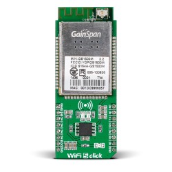
Ever since the start of the MikroE. Learn pages, we have covered a significant number of radio modules. We went over Bluetooth Low Energy, LoRa RF, GSM, EnOcean and NRF. Today, we are going to cover one more radio: WiFi 5 click board. We will not go into depth on how WiFi actually works, for this occasion, we will do a simple "getting started guide": we will connect to a WiFi network, make a RESTful request, retrieve the data, and parse the response. We will use an online service for getting weather information called OpenWeatherMap. We will parse the desired information, and print to our TFT display.
Getting to know the GainSpan 1500M

The module communicates with an MCU through UART or SPI interfaces using simple commands. The module supports Wi-Fi PHY rates up to 72.2 Mbps. It is fully compliant with 802.11b/g/n. The module can run a full WiFi and TCP/IP network stack, and therefore no need of implementing a stack on the MCU is needed. But, for those who are adventurous, you can also implement a protocol stack of your own on the MCU, and just use the WIFI5 for signal throughput. Also, the module provides WEP/WPA/WPA2 security, Adhoc as well as Wi-Fi Protected Setup (WPS) for ease of provisioning.
For our little example, we will run the protocol stack on the WIFI5 Click, allowing our host MCU to do other tasks (data parsing, for example). We will send a couple of serial commands through UART, which are needed to set up the module right. This perfectly demonstrates the ease of use of this click, as we can establish a connection and get data of the web by just running a couple serial commands. With that said... let's get to work!

Running the example
Let's get step by step overview of how our example works. Fist off, our MCU communicates with the WiFi5 using UART. The WiFi 5 returns specific message responses which we store into our receiving buffer and parse from there on. We are anticipating a response which looks like this: "OKrnrn". When we catch this response, we set a flag which notifies us that we got a positive response, and that we can go on the send the next command.
Let's start with some code, we will include the necessary libraries
#include#include // TFT module connections unsigned int TFT_DataPort at GPIOE_ODR; sbit TFT_RST at GPIOE_ODR.B8; sbit TFT_RS at GPIOE_ODR.B12; sbit TFT_CS at GPIOE_ODR.B15; sbit TFT_RD at GPIOE_ODR.B10; sbit TFT_WR at GPIOE_ODR.B11; sbit TFT_BLED at GPIOE_ODR.B9; // End TFT module connections volatile uint32_t bfr_ctr = 0; volatile uint8_t serial_buffer[1000] = {0}; bool response_finished; bool ok_response; bool first_flag;
Let's look at how we are implementing these flags:
void wifi5_rx_isr( char rx_input )
{

        if (rx_input == 'K')
        {
            if (serial_buffer[bfr_ctr - 1] == 'O')
               ok_response = true;
        }

        if (rx_input == 'n' && ok_response == true && serial_buffer[bfr_ctr - 1] == 'r')
        {
            if (first_flag != true) first_flag = true;
            else if (rx_input == 'n' && first_flag == true && serial_buffer[bfr_ctr - 1] == 'r')
                response_finished = true;
        }
        serial_buffer[bfr_ctr++] = rx_input;

}
Our function takes up the byte which we receive through the UART. When we detect an "OK" response, we will raise our ok_response flag, after that, we are anticipating two "rn" in a row. When we detect the first "rn", we set the first_flag to true, this means that we have one "rn" and that we need to anticipate the final one. Finally, when we get the last "rn" response, we can raise the response_finished flag, which will notify us that we have got a full successful response. At the end, the received byte will be stored in our receive buffer.
Let's get a quick overview of our interrupt function
void WF_RX_ISR() iv IVT_INT_USART3 ics ICS_AUTO
{
     char tmp;
     if( RXNE_USART3_SR_bit == 1)
     {
         if (bfr_ctr == 999)
         {
           UART1_WRITE_TEXT("CTR OVERFLOW");
           while(1);
         }
        tmp = USART3_DR;
        wifi5_rx_isr(tmp);
     }
}
First we check if our buffer has reached a maximum, to avoid having a buffer overflow, if our buffer counter is nearing the end, we will stop the execution of our program and run an infinite while loop. If, however, our buffer has enough space, we will transfer this byte to our parsing function, which I have described in the paragraph above.
Also, after executing every command successfully, we need to reset our flags to false, so that we can anticipate the responses again:
void flags_false ()
{
    response_finished = false;
    ok_response = false;
    first_flag = false;
}
And, reset the receiving buffer so that we can receive our new messages again:
void clear_serial_buffer()
{
  uint32_t i;

  NVIC_IntDisable( IVT_INT_USART3 );

  for (i=0; i<1000; i++)
      serial_buffer[i] = 0;

  bfr_ctr = 0;

  NVIC_IntEnable( IVT_INT_USART3 );
}
Now comes a little bit messier part. Once we receive the weather data from the site in the form of an xml, we need to find the right data in it. The function looks like this:
void parse_data ()
{
   static volatile char *xml_ptr;
   char city_str[9];
   char temperature_string[12];
   char humidity_string[8];
   char pressure_string[10];
   int temp;


   xml_ptr = strstr(serial_buffer, "name");

   strncpy(city_str, xml_ptr+6, 8);
   city_str[8]='';

   TFT_Write_Text("City: ",10,10);
   TFT_Write_Text(city_str, 50,10);

   xml_ptr = strstr(serial_buffer, "temperature value");
   strncpy(temperature_string, xml_ptr+19, 5);
   temperature_string[5] = '';

   temp = atoi(temperature_string);
   temp = temp - 273;
   inttostr(temp, temperature_string);
   TFT_Write_Text("Temperature: ", 10,30);
   TFT_Write_Text(temperature_string, 100,30);
   TFT_Write_Text("Celsius", 200,30);

   xml_ptr = strstr(serial_buffer,"humidity value=");
   strncpy(humidity_string, xml_ptr+16, 2);
   humidity_string[2] = '';
   TFT_Write_Text("Humidity: ", 10,50);
   TFT_Write_Text(humidity_string, 110,50);
   TFT_Write_Text("%", 200,50);

   xml_ptr = strstr(serial_buffer,"pressure value=");
   strncpy(pressure_string, xml_ptr+16, 4);
   pressure_string [4] = '';
   TFT_Write_Text("Pressure: ", 10,70);
   TFT_Write_Text(pressure_string, 110,70);
   TFT_Write_Text("hPa ", 200,70);

}
What we are doing here is actually simple, we search for a specific string in our receive buffer, the strstr function will return a pointer to the first letter of that string. After that we will increment the pointer so that we can get to our desired data. Once, we acquire the desired data, we will print it out on the TFT display.
Speaking of the TFT display, here's a simple function to initialize it:
void display_init()
{
  TFT_Init_ILI9341_8bit(320, 240);
  TFT_Set_Pen(CL_BLACK, 1);
  TFT_Set_Font(TFT_defaultFont, CL_BLACK, FO_HORIZONTAL);
  TFT_Fill_Screen(CL_Aqua);

  TFT_Write_Text("TFT INITIALIZED",10,10);
  Delay_ms(1000);
  TFT_Fill_Screen(CL_Aqua);
  Delay_ms(1000);
}
At last, let's look at our main function:
void main()
{
     // initialize the UART for monitoring the program
     UART1_Init_Advanced( 9600,  _UART_8_BIT_DATA,
                                  _UART_NOPARITY,
                                 _UART_ONE_STOPBIT,
                                 &_GPIO_MODULE_USART1_PA9_10 );
     Delay_ms(300);
     UART1_Write_Text("Uart initializedrn");

     Delay_ms(5000);
     // initialize the UART for communication between the MCU and the WiFi 5 Click
     UART3_Init_Advanced( 9600, _UART_8_BIT_DATA,
                                _UART_NOPARITY,
                                _UART_ONE_STOPBIT,
                                &_GPIO_MODULE_USART3_PD89);

     Delay_ms(5000);


     UART1_Write_Text("Uarts readyrn");

     Delay_ms(1000);

     // set up the UART interrupt
     RXNEIE_USART3_CR1_bit = 1;
     NVIC_IntEnable( IVT_INT_USART3 );
     EnableInterrupts();

     // clear the buffer and the flags, setting them ready for the program to start
     clear_serial_buffer();
     flags_false();
     UART3_WRITE_TEXT("AT+WPAPSK=MikroE Public,mikroe.guestrn");  // compute the PSK from SSID and PassPhrase
     while(response_finished == false);                             // wait for the "OK" response

     UART1_WRITE_TEXT(serial_buffer);                               // print out the response

     clear_serial_buffer();                                         // clear the buffer and flags
     flags_false();
     Delay_ms(300);
     UART3_WRITE_TEXT("AT+WA=MikroE Publicrn");                   // try to connect to MikroE Public network
     while (response_finished == false);                            // wait for the "OK" response

     UART1_WRITE_TEXT(serial_buffer);                               // Print out the response

     clear_serial_buffer();                                         // clear the buffer and flags
     flags_false();
     UART3_WRITE_TEXT("at+httpopen=api.openweathermap.orgrn");    // open the api.openweathermap.org web page
     while (response_finished == false);                            // wait for the "OK" response

     UART1_WRITE_TEXT(serial_buffer);                               // print out the buffer

     clear_serial_buffer();                                         // clear the buffer and the flags
     flags_false();
     UART3_WRITE_TEXT("at+httpconf=11,api.openweathermap.orgrn"); // configure the right http parameters
     while (response_finished == false);                            // wait for the "OK" response

     UART1_WRITE_TEXT(serial_buffer);                               // print out the buffer

     clear_serial_buffer();                                         // clear the buffer and the flags
     flags_false();
     UART3_WRITE_TEXT("at+httpsend=0,1,5,/data/2.5/weather?q=Belgrade&mode=xml&appid=438f494400615270b4d2c1f9d563bf19rn"); // send the http request


     while(bfr_ctr <  834);                           // wait until the buffer fills up with data
     uart1_write_text("Data fetched rnrn");       // notify the user that we have fetched the data from the web

//********** PARSING PART***********************//

       display_init();                                // initialize the TFT display
       parse_data();                                  // parse the data and display it on the TFT

}
The main looks complicated, but in reality it's pretty simple. We are sending the required commands and waiting for successful responses, if it all goes well, at the end we send the http request, wait for the buffer to fills up with data, then parse and display that data.
When using a serial monitor, the whole process should look like this:

So there it is! It's that simple: run a few serial commands, make the right data parser, and you can get data of the net easily! GainSpan did a good job by making a module this easy to use.
Source code can be found on either Libstock or Github.
If you liked this tutorial, and you are a radio modules fan, stick around! More radios coming our way in the next weeks!


