


OFF
GO LOCAL
| Company | Stock | Price |
|---|---|---|


MIKROE-6584
16 g
Status:
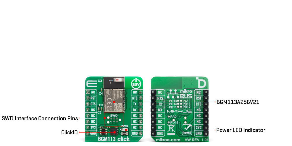
BGM113 Click is a compact add-on board that provides Bluetooth low energy connectivity for embedded applications, offering a complete solution for wireless communication and secure data exchange. It is based on the BGM113A256V21 wireless Gecko Bluetooth module from Silicon Labs, which integrates the radio, onboard Bluetooth stack, and GATT-based profiles while also being capable of hosting end-user applications. Powered by a 32-bit ARM Cortex-M4 core running at 38.4MHz with 256kB of flash memory and 32kB of RAM, the module delivers efficient performance, while its integrated antenna ensures robust 2.4GHz communication with a TX power of up to +3dBm and RX sensitivity down to -92dBm, achieving ranges up to 50 meters. BGM113 Click is ideal for IoT sensors, health and wellness devices, industrial and building automation, commercial and retail systems, and smart accessories for smartphones, tablets, and PCs.
BGM113 Click is fully compatible with the mikroBUS™ socket and can be used on any host system supporting the mikroBUS™ standard. It comes with the mikroSDK open-source libraries, offering unparalleled flexibility for evaluation and customization. What sets this Click board™ apart is the groundbreaking ClickID feature, enabling your host system to automatically detect and identify this add-on board.
This product is no longer in stock
Availability date:
OFF
| Company | Stock | Price |
|---|---|---|
BGM113 Click is based on the BGM113A256V21, a wireless Gecko Bluetooth module from Silicon Labs that brings reliable Bluetooth low energy connectivity into embedded applications. The BGM113A256V21 provides an all-in-one solution that integrates radio, Bluetooth stack, and GATT-based profiles while also being capable of hosting end-user applications. Powered by a 32-bit ARM Cortex-M4 core running at 38.4MHz with 256kB of flash memory and 32kB of RAM, the module ensures efficient operation for a wide range of IoT and embedded use cases. Its Bluetooth 4.2 compliance and onboard Bluetooth Smart stack enable easy integration, while the integrated antenna supports communication across the 2.4GHz band with a TX output power up to +3dBm and RX sensitivity down to -92dBm, allowing a reliable connection range of up to 50 meters.
The BGM113A256V21 also incorporates an autonomous hardware crypto accelerator and random number generator, ensuring secure communication in sensitive applications. With its low power design, onboard resources, and strong RF performance, BGM113 Click is an excellent choice for IoT sensors, health and wellness devices, industrial and building automation systems, commercial and retail solutions, as well as accessories for smartphones, tablets, and PCs where stable, secure, and energy-efficient Bluetooth connectivity is required.
This Click board™ establishes communication between the BGM113A256V21 module and the host MCU through a UART interface, using standard UART RX and TX pins and hardware flow control via CTS and RTS pins. The default communication speed is set at 115200bps, ensuring efficient data exchange. Along with the communication and control pins, this Click board™ also includes a reset pin (RST) enabling easy module resetting, and SWD pads designed for use with MIKROE's 6-pin Needle Cable, providing an optional flash and debug SWD (Serial Wire Debug) interface functionality.
On the back side of the board, the remaining GPIO pins of the module are exposed in the form of test points, allowing easy access for evaluation, debugging, or expansion purposes. Each of these GPIO pins can be individually configured as either an input or an output, providing flexibility for a wide range of application requirements. In addition to the basic configurations, the module also supports more advanced modes, such as open-drain and open-source operation, enabling interfacing with different logic levels and external components.
This Click board™ can be operated only with a 3.3V logic voltage level. The board must perform appropriate logic voltage level conversion before using MCUs with different logic levels. It also comes equipped with a library containing functions and example code that can be used as a reference for further development.
Type
2.4 GHz Transceivers,BT/BLE
Applications
Ideal for IoT sensors, health and wellness devices, industrial and building automation, commercial and retail systems, and smart accessories for smartphones, tablets, and PCs
On-board modules
BGM113A256V21 - wireless Gecko Bluetooth® module from Silicon Labs
Key Features
Integration of radio, onboard Bluetooth stack and GATT-based profiles, 32-bit ARM Cortex-M4 core, autonomous hardware crypto accelerator with random number generator, Bluetooth 4.2 compliance, integrated 2.4GHz antenna, UART interface with hardware flow control, SWD pads for optional flash and debug access, GPIO pins exposed as test points, and more
Interface
UART
Feature
ClickID
Compatibility
mikroBUS™
Click board size
S (28.6 x 25.4 mm)
Input Voltage
3.3V
This table shows how the pinout on BGM113 Click corresponds to the pinout on the mikroBUS™ socket (the latter shown in the two middle columns).
| Notes | Pin | Pin | Notes | ||||
|---|---|---|---|---|---|---|---|
| NC | 1 | AN | PWM | 16 | NC | ||
| Reset / ID SEL | RST | 2 | RST | INT | 15 | RTS | UART RTS |
| UART CTS / ID COMM | CTS | 3 | CS | RX | 14 | TX | UART TX |
| NC | 4 | SCK | TX | 13 | RX | UART RX | |
| NC | 5 | MISO | SCL | 12 | NC | ||
| NC | 6 | MOSI | SDA | 11 | NC | ||
| Power Supply | 3.3V | 7 | 3.3V | 5V | 10 | NC | |
| Ground | GND | 8 | GND | GND | 9 | GND | Ground |
| Label | Name | Default | Description |
|---|---|---|---|
| LD1 | PWR | - | Power LED Indicator |
| Description | Min | Typ | Max | Unit |
|---|---|---|---|---|
| Supply Voltage | - | 3.3 | - | V |
| Frequency Range | - | 2.4 | - | GHz |
| TX Power | - | - | +3 | dBm |
| RX Sensitivity | - | -92 | - | dBm |
| Communication Range | - | - | 50 | m |
BGM113 Click demo application is developed using the NECTO Studio, ensuring compatibility with mikroSDK's open-source libraries and tools. Designed for plug-and-play implementation and testing, the demo is fully compatible with all development, starter, and mikromedia boards featuring a mikroBUS™ socket.
Example Description
This example demonstrates the usage of the BGM113 Click board. The application initializes the module, resets the device, checks communication, retrieves the BT address, and manages bondings. It also configures the device to be discoverable and bondable and handles various BT-related events such as connection state changes, security mode, and GATT operations.
Key Functions
bgm113_cfg_setup This function initializes Click configuration structure to initial values.bgm113_init This function initializes all necessary pins and peripherals used for this Click board.bgm113_send_packet This function sends a desired command packet from the Click context object.bgm113_read_packet This function reads an event or response packet from the ring buffer and stores it in the Click context object.bgm113_set_gap_mode This function configures the current BT LE GAP Connectable and Discoverable modes.Application Init
Initializes the logger and sets up the BGM113 Click configuration. Resets the device, checks communication, retrieves the BT address, and deletes existing bondings. Configures the device to be bondable and sets LE GAP modes.
Application Task
Continuously reads packets from the BGM113, parses the contents, and logs relevant information regarding system events, BT connections, and bonding information.
Application Output
This Click board can be interfaced and monitored in two ways:
Additional Notes and Information
The complete application code and a ready-to-use project are available through the NECTO Studio Package Manager for direct installation in the NECTO Studio. The application code can also be found on the MIKROE GitHub account.
NOTE: Please be advised that any peripheral devices or accessories shown connected to the Click board™ are not included in the package. Check their availability in our shop or in the YMAN section below.

$50.00

$889.00

$95.00

$549.00

$299.00

$29.00

$29.00

$6.59

$3.60

$119.00

$449.00

$349.00

$349.00

$349.00

$299.00

$269.00

$249.00

$209.00
