


OFF
GO LOCAL
| Company | Stock | Price |
|---|---|---|


MIKROE-1423
35 g
Status:
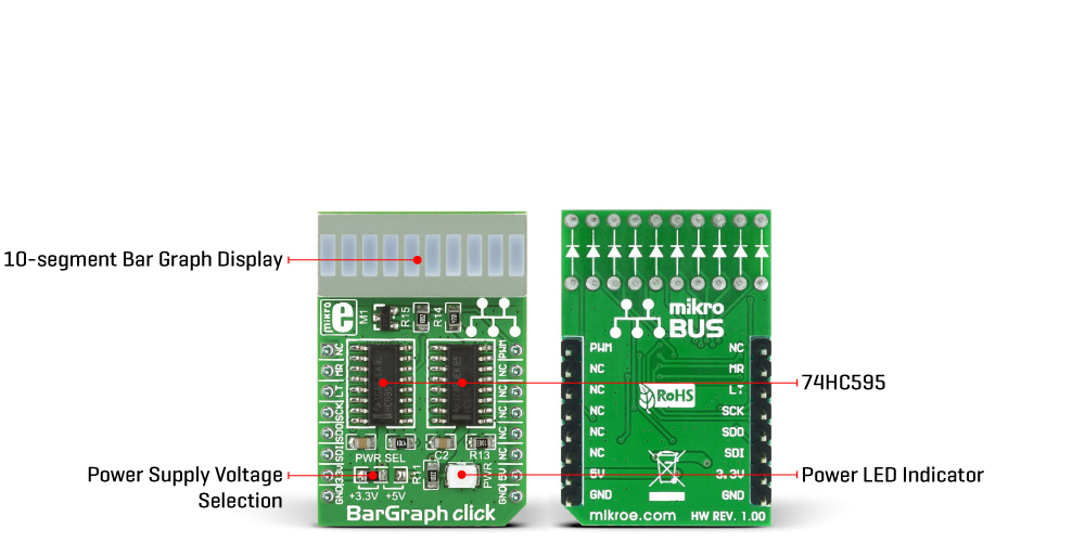
BarGraph Click is a compact add-on board with an LED bar graph display. This board features two SN74HC595Ds, 8-bit shift registers with 3-state output registers from Texas Instruments. The LED bar graph display consists of 10 red LEDs, and you can control each LED separately, including the light intensity. The segments of the onboard bar graph LED display are bright and uniformly colored, providing pleasant and clean visual feedback. This Click board™ makes the perfect solution for displaying various signal or status properties, building VU-meters, and various types of gauges and signal indicators, whether it be an audio level, current/voltage level, the position of the encoder, or any other property that can be displayed in the form of a bar graph.
BarGraph Click is supported by a mikroSDK compliant library, which includes functions that simplify software development. This Click board™ comes as a fully tested product, ready to be used on a system equipped with the mikroBUS™ socket.
This product is no longer in stock
Availability date:
OFF
| Company | Stock | Price |
|---|---|---|
BarGraph Click is based on two SN74HC595Ds, 8-bit shift registers with 3-state output registers from Texas Instruments. The SN74HC595Ds are comprised of a D-type internal storage register and the serial-to-parallel shift register, both 8 bits wide. Each of these registers has its clock line, making it possible to clock in the desired data and then clock it out to the parallel output pins. The shift registers are connected in a cascade. It is worth mentioning that the Q7S of the last SN74HC595D is routed to the MISO pin of the mikroBUS™, labeled as the SDO, allowing connection of multiple devices in cascade, building more complex setups. Adding more devices in the cascade would require more 8-bit words to be clocked into the first SN74HC595D in the chain.
The shift registers power the JSB-R102510ZR, a 10-segment single-color light bar from Ningbo Junsheng Electronics. Each LED has its anode and cathode routed out, making each LED element independent so that it can be used in any circuit configuration. However, the JSB-R102510ZR bar graph display is connected as a display with the common cathode, meaning that all LED cathodes are connected to a single point. This LED cathodes common line (CC) is connected to the drain of the N channel MOSFET, while its source is connected to the GND. Driving this MOSFET via its gate through the PWM pin of the mikroBUS™ allows the dimming of the LED segments. By changing the duty cycle of the PWM signal, it is possible to change the brightness of the JSB-R102510ZR bar graph display. The gate of this MOSFET is connected to the PWM pin of the mikroBUS™, and it is pulled to VCC, allowing the display to work if the PWM pin is left floating.
The Click board™ communicates with the host MCU via the mikroBUS™ SPI interface pins. Two bytes of information (16 bits in total) are pushed through the serial data input pin (DS) of the first SN74HC595D and routed to the SDI pin. The SN74HC595D construction is such that after receiving 8 bits, clocking in one more bit will shift the existing 8 bits by one place, overflowing the last bit to the Q7S output pin and shifting it out that way. Since the Q7S of the first SN74HC595D is connected to the DS pin of the second 74HC595, clocking 16 bits into the first SN74HC595D will fill up both ICs with the required data. Note that only two bits of the second byte will be used since the second shift register only has two outputs connected to the bar graph display (8 from the first IC + 2 from the second).
When the data has been clocked in, the SPI clock should be stopped, and the CS pin should be driven to a HIGH logic level. The CS pin of the mikroBUS™ is routed to the STCP pin of the SN74HC595Ds and labeled as LT on the Click board™. A rising edge on the STCP input pins of the SN74HC595Ds will latch the data from their internal storage registers to the output pins, polarizing the connected bar graph segment anodes. The onboard resistor pulls the STCP pin to a LOW logic level. If the previously mentioned MOSFET is in a conductive state, the current can flow through the LEDs, and the polarized LED elements will get lit.
The #MR pin is used to clear the data in the internal storage register of the ICs. The LOW logic level on this pin will clear the content of this storage register, but it will not turn off the already activated outputs. The #MR pin is routed to the default RST pin position of the mikroBUS™, labeled as MR, and it is pulled to a HIGH logic level by the onboard resistor.
This Click board™ can operate with either 3.3V or 5V logic voltage levels selected via the PWR SEL jumper. This way, both 3.3V and 5V capable MCUs can use the communication lines properly. However, the Click board™ comes equipped with a library containing easy-to-use functions and an example code that can be used, as a reference, for further development.
Type
Bargraph,LED Segment
Applications
Can be used for displaying various signal or status properties, building VU-meters, and various types of gauges and signal indicators, whether it be an audio level, current/voltage level, the position of the encoder, or any other property that can be displayed in a form of a bar graph
On-board modules
SN74HC595D - 8-bit shift registers with 3-state output registers from Texas Instruments
JSB-R102510ZR – 10-segment single-color light bar from Ningbo Junsheng Electronics
Key Features
Clean and bright bar graph LED display, with uniform light disbursement, simple to use with included software library functions, low current consumption per LED, it is possible to serially connect more devices, and more
Interface
GPIO,PWM,SPI
Feature
No ClickID
Compatibility
mikroBUS™
Click board size
M (42.9 x 25.4 mm)
Input Voltage
3.3V or 5V
This table shows how the pinout on BarGraph click corresponds to the pinout on the mikroBUS™ socket (the latter shown in the two middle columns).
| Notes | Pin | Pin | Notes | ||||
|---|---|---|---|---|---|---|---|
| NC | 1 | AN | PWM | 16 | PWM | Dimming PWM IN | |
| Memory Reset Input | MR | 2 | RST | INT | 15 | NC | |
| Latch Input | LT | 3 | CS | RX | 14 | NC | |
| SPI Clock | SCK | 4 | SCK | TX | 13 | NC | |
| SPI Data OUT | SDO | 5 | MISO | SCL | 12 | NC | |
| SPI Data IN | SDI | 6 | MOSI | SDA | 11 | NC | |
| Power supply | 3.3V | 7 | 3.3V | 5V | 10 | 5V | Power supply |
| Ground | GND | 8 | GND | GND | 9 | GND | Ground |
| Label | Name | Default | Description |
|---|---|---|---|
| LD1 | PWR | - | Power LED indicator |
| JP1 | VCC SEL | Right | Power supply voltage selection: left position 3.3V, right position 5V |
We provide a library for the BarGraph Click as well as a demo application (example), developed using MIKROE compilers. The demo can run on all the main MIKROE development boards.
Package can be downloaded/installed directly from NECTO Studio Package Manager (recommended), downloaded from our LibStock™ or found on Mikroe github account.
Library Description
This library contains API for BarGraph Click driver.
Key functions
Functions for initializes the chip.
Functions for reset the chip.
Displays function.
Example Description
This application uses a high-quality bar graph LED display.
 void application_task ( void )
 {
     for ( cnt = 0; cnt <= 10; cnt++ )
     {
         bargraph_display( &bargraph, cnt );
         Delay_ms( 500 );
     }
 }
The full application code, and ready to use projects can be installed directly from NECTO Studio Package Manager (recommended), downloaded from our LibStock™ or found on Mikroe github account.
Other Mikroe Libraries used in the example:
Additional notes and informations
Depending on the development board you are using, you may need USB UART click, USB UART 2 Click or RS232 Click to connect to your PC, for development systems with no UART to USB interface available on the board. UART terminal is available in all MIKROE compilers.
This Click board™ is supported with mikroSDK - MIKROE Software Development Kit. To ensure proper operation of mikroSDK compliant Click board™ demo applications, mikroSDK should be downloaded from the LibStock and installed for the compiler you are using.
For more information about mikroSDK, visit the official page.
NOTE: Please be advised that any peripheral devices or accessories shown connected to the Click board™ are not included in the package. Check their availability in our shop or in the YMAN section below.

$889.00

$95.00

$549.00

$299.00

$29.00

$29.00

$6.59

$3.60

$119.00

$349.00

$299.00

$449.00

$349.00

$349.00

$269.00

$249.00

$209.00
