


OFF
GO LOCAL
| Company | Stock | Price |
|---|---|---|


MIKROE-6815
23 g
Status:
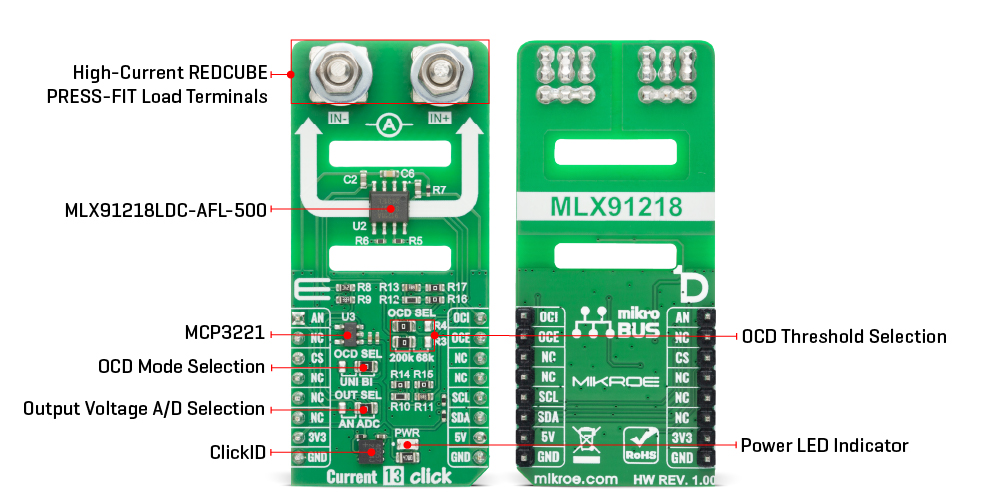
Current 13 Click is a compact add-on board designed for high-speed current measurement in demanding automotive and industrial applications. It is based on the MLX91218 (MLX91218LDC-AFL-500), a high-accuracy IMC-Hall® current sensor IC from Melexis with integrated overcurrent detection (OCD) and AEC-Q100 Grade 0 automotive qualification. This IC features a dual overcurrent detection system with selectable unidirectional and bidirectional sensing modes, adjustable OCD threshold configuration via onboard jumpers, and flexible output selection between analog and digital conversion using the MCP3221 12-bit ADC. With a measurement range of ±10mT, current range up to 200A, 600mV/mT sensitivity, 400kHz bandwidth, and very low thermal drift, it ensures reliable operation even in fast-switching environments. Designed for use with the optional U-Shield Ni-Fe ferromagnetic core, Current 13 Click is ideal for high-voltage traction inverters, DC-DC converters, battery management systems, and smart fuse or overcurrent protection applications.
Current 13 Click is fully compatible with the mikroBUS™ socket and can be used on any host system supporting the mikroBUS™ standard. It comes with the mikroSDK open-source libraries, offering unparalleled flexibility for evaluation and customization. What sets this Click board™ apart is the groundbreaking ClickID feature, enabling your host system to automatically detect and identify this add-on board.
This product is no longer in stock
Availability date:
OFF
| Company | Stock | Price |
|---|---|---|
Current 13 Click is based on the MLX91218 (MLX91218LDC-AFL-500), a high-speed, high-accuracy IMC-Hall® current sensor IC with integrated overcurrent detection (OCD) from Melexis, designed for precise and fast current measurement in high-performance automotive and industrial applications. This monolithic Hall-effect sensor uses IMC-Hall® technology to provide an analog output voltage proportional to the magnetic flux density parallel to the IC surface. Its transfer characteristic is factory-trimmed over temperature to ensure exceptional linearity and accuracy, while key parameters such as offset, sensitivity, filtering, and internal overcurrent threshold can be programmed during end-of-line calibration. Typical use cases include redundant current monitoring in battery management systems (BMS), phase and DC-link current measurement in high-voltage traction motor inverters, 48V boost recuperation inverters, DC-DC converters, smart battery junction boxes, and smart fuse overcurrent detection circuits.
The MLX91218 offers a measurement range ±10mT, current from 1 to 200A, featuring a fixed output mode with a low-field IMC core, sensitivity of 600mV/mT, and an overcurrent detection level at 134.7% of full scale. With AEC-Q100 Grade 0 automotive qualification and extremely low thermal drift across a wide temperature range, this device ensures reliability and stability under demanding conditions. Thanks to its 400kHz bandwidth and ultra-fast response time, it is ideally suited for high-speed switching environments such as inverters, converters, and motor control systems that require rapid current feedback.
Current 13 Click features a dual overcurrent detection (OCD) configuration system that allows flexible adaptation to various application requirements. The board includes an OCD SEL jumper that provides two selectable modes: UNI and BI, enabling either unidirectional or bidirectional current sensing configuration. Additionally, the board integrates a dedicated set of OCD SEL jumpers labeled R3 and R4 that enable fine-tuning of the OCD threshold level. By adjusting these jumpers, users can define the desired overcurrent detection point according to system safety requirements and protection logic. Furthermore, two dedicated pins, OCI and OCE, provide feedback signals corresponding to overcurrent detection events based on the internal and external threshold levels, respectively.
The MLX91218's output signal can be converted to a digital value using MCP3221, a successive approximation A/D converter with a 12-bit resolution from Microchip, using a 2-wire I2C compatible interface, or sent directly to an analog pin of the mikroBUS™ socket labeled as AN. Selection can be performed via an onboard SMD jumper labeled OUT SEL, placing it in an appropriate position marked as AN and ADC.
In a typical current sensing setup, Current 13 Click is designed to operate in combination with a U-shaped ferromagnetic shield, the Ferromagnetic Shield U-Shield Ni-Fe, which MIKROE also provides as an accessory. By using this U-shaped shield, the MLX91218 sensor can be mounted directly over a bus bar while being electrically isolated from it by the PCB, allowing safe and accurate current measurement without direct electrical contact. The board includes a clearly marked placement area that matches the geometry of the U-Shield, ensuring straightforward and reliable mechanical integration.
This Click board™ can operate with either 3.3V or 5V logic voltage levels. he onboard design uses a dual-voltage scheme in which 5V is dedicated to powering the MLX91218 IC, providing stable operation and maintaining the sensor’s specified accuracy and performance, while 3.3V is used for communication with the host MCU. The board must perform appropriate logic voltage level conversion before using MCUs with different logic levels. It also comes equipped with a library containing functions and example code that can be used as a reference for further development.
Type
Current,Current sensor
Applications
Ideal for high-voltage traction inverters, DC-DC converters, battery management systems, and smart fuse or overcurrent protection applications
On-board modules
MLX91218LDC-AFL-500 - high speed high Accuracy IMC-Hall® current sensor IC in with OCD from Melexis
Key Features
High-speed and high-accuracy IMC-Hall® current sensor, dual OCD configuration with selectable unidirectional and bidirectional sensing modes, adjustable OCD threshold level, selectable analog or digital output, low thermal drift across a wide temperature range, AEC-Q100 Grade 0 automotive qualification, compatibility with U-Shield Ni-Fe ferromagnetic core for precise magnetic field focusing, and more
Interface
I2C
Feature
ClickID
Compatibility
mikroBUS™
Click board size
L (57.15 x 25.4 mm)
Input Voltage
3.3V,5V
This table shows how the pinout on Current 13 Click corresponds to the pinout on the mikroBUS™ socket (the latter shown in the two middle columns).
| Notes | Pin | Pin | Notes | ||||
|---|---|---|---|---|---|---|---|
| Analog Current Output | AN | 1 | AN | PWM | 16 | OCI | Internal Threshold Overcurrent Detection |
| NC | 2 | RST | INT | 15 | OCE | External Threshold Overcurrent Detection | |
| ID COMM | CS | 3 | CS | RX | 14 | NC | |
| NC | 4 | SCK | TX | 13 | NC | ||
| NC | 5 | MISO | SCL | 12 | SCL | I2C Clock | |
| NC | 6 | MOSI | SDA | 11 | SDA | I2C Data | |
| Power Supply | 3.3V | 7 | 3.3V | 5V | 10 | 5V | Power Supply |
| Ground | GND | 8 | GND | GND | 9 | GND | Ground |
| Label | Name | Default | Description |
|---|---|---|---|
| LD1 | PWR | - | Power LED Indicator |
| JP1 | OUT SEL | Right | Output Voltage A/D Selection AN/ADC: Left position AN, Right position ADC |
| JP2 | OCD SEL | Right | OCD Mode Selection UNI/BI: Left position UNI, Right position BI |
| JP3-JP4 | OCD SEL | Left | OCD Threshold Selection 200k/68k: Left position 200k, Right position 68k |
| Description | Min | Typ | Max | Unit |
|---|---|---|---|---|
| Supply Voltage | 3.3 | - | 5 | V |
| Current Range | 1 | - | 200 | A |
| Operational Magnetic Field Range | - | - | ±10 | mT |
| Programmable Sensitivity | 200 | 600 | 600 | mV/mT |
Current 13 Click demo application is developed using the NECTO Studio, ensuring compatibility with mikroSDK's open-source libraries and tools. Designed for plug-and-play implementation and testing, the demo is fully compatible with all development, starter, and mikromedia boards featuring a mikroBUS™ socket.
Example Description
This example demonstrates the use of Current 13 Click board by reading and displaying the input current measurements.
Key Functions
current13_cfg_setup This function initializes Click configuration structure to initial values.current13_init This function initializes all necessary pins and peripherals used for this Click board.current13_calib_offset This function calibrates the zero current offset value.current13_calib_resolution This function calibrates the data resolution at the known load current.current13_read_current This function reads the input current level [A].Application Init
Initializes the driver and calibrates the zero current offset and data resolution at 3A load current.
Application Task
Reads the input current measurements and displays the results on the USB UART approximately once per second.
Application Output
This Click board can be interfaced and monitored in two ways:
Additional Notes and Information
The complete application code and a ready-to-use project are available through the NECTO Studio Package Manager for direct installation in the NECTO Studio. The application code can also be found on the MIKROE GitHub account.
NOTE: Please be advised that any peripheral devices or accessories shown connected to the Click board™ are not included in the package. Check their availability in our shop or in the YMAN section below.

$9.00

$889.00

$95.00

$549.00

$299.00

$29.00

$29.00

$6.59

$3.60

$119.00

$449.00

$349.00

$349.00

$349.00

$299.00

$269.00

$249.00

$209.00
