


OFF
GO LOCAL
| Company | Stock | Price |
|---|---|---|


MIKROE-6686
17 g
Status:
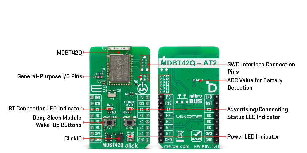
MDBT42Q Click is a compact add-on board that provides Bluetooth Low Energy connectivity for short-range wireless communication for embedded applications. It is based on the MDBT42Q-AT2 module from RAYTAC, built around the Nordic nRF52810 SoC. This module combines a 32-bit ARM Cortex-M4F processor with 192kB Flash and 24kB RAM, and comes preloaded with RAYTAC’s AT command firmware for easy configuration over UART in the peripheral/slave role. Key features include support for Bluetooth 5.2/5.1/5.0/5.4 specifications, selectable on-air data rates of 1Mbps or 2Mbps, five TX power levels, low-power modes with GPIO wake-up, and an onboard chip antenna for excellent connectivity. MDBT42Q Click is ideal for IoT devices, wireless sensors, smart home systems, asset tracking, and healthcare or fitness monitoring applications.
MDBT42Q Click is fully compatible with the mikroBUS™ socket and can be used on any host system supporting the mikroBUS™ standard. It comes with the mikroSDK open-source libraries, offering unparalleled flexibility for evaluation and customization. What sets this Click board™ apart is the groundbreaking ClickID feature, enabling your host system to automatically detect and identify this add-on board.
This product is no longer in stock
Availability date:
OFF
| Company | Stock | Price |
|---|---|---|
MDBT42Q Click is based on the MDBT42Q-AT2 module from RAYTAC designed to provide Bluetooth Low Energy (BLE) connectivity. This certified BT 5.2 stack module is based on the Nordic nRF52810 SoC, a highly integrated solution that combines a 32-bit ARM Cortex-M4F processor with 192kB of Flash memory and 24kB of RAM, ensuring efficient operation in wireless applications. Acting exclusively in the peripheral/slave role, the module comes preloaded with RAYTAC’s AT command firmware, which simplifies configuration and control through a UART interface. As a recommended third-party module by Nordic Semiconductor, MDBT42Q-AT2 meets multiple international standards, being certified for FCC, IC, CE, Telec (MIC), KC, SRRC, and NCC compliance, while its onboard chip antenna guarantees excellent connectivity performance in compact embedded designs.
The module offers flexible configuration options, allowing users to choose on-air data rates of either 1Mbps or 2Mbps, set transmission power across five selectable levels, and adjust advertising time. For better user interaction, it supports customizable LED indication patterns that reflect advertising and connection status, with a yellow CONN/ADV LED as a clear status marker. To optimize energy consumption, it provides both DC-to-DC and LDO power modes, a dedicated power-down state with GPIO wake-up support, and efficient use of resources to extend battery life in portable systems.
Its data handling capabilities include support for a maximum MTU size of 247 bytes, enabling payloads of up to 244 bytes, ensuring reliable and flexible data exchange in BLE applications. With these features, MDBT42Q Click is ideal for IoT devices, wireless sensors, smart home automation, asset tracking systems, healthcare and fitness monitors, and other scenarios where low-power, short-range wireless connectivity is required.
This Click board™ establishes communication between the MDBT42Q-AT2 module and the host MCU through a UART interface, using standard UART RX and TX pins and hardware flow control via CTS and RTS pins. The default communication speed is set at 115200bps, ensuring efficient data exchange. In addition to the UART pins for communication with the module, this Click board also features a PD active-high pin used to enable the UART interface, a reset pin (RST) enabling easy module resetting, blue IND LED indicator for Bluetooth connection status (also available through IND pin), and SWD pads designed for use with MIKROE's 6-pin Needle Cable, providing an optional flash and debug SWD (Serial Wire Debug) interface functionality.
The board integrates dedicated wake-up buttons that provide a reliable way to bring the module out of deep sleep mode. Since the wake-up mechanism is logic-selective, it requires a clearly defined signal transition to activate the module, which is why two separate buttons are provided: one tied to the 3V3 rail and the other to GND. By pressing either of these, a valid high or low logic level is momentarily introduced, triggering the wake-up event in accordance with the module’s power management logic.
The board is also equipped with a set of carefully placed test points that provide developers with easy access to key signals for debugging, monitoring, and feature expansion. A dedicated group of test points labeled P12 through P19 enables support for up to eight programmable GPIO outputs, offering flexibility to configure these pins according to application requirements. In addition to general-purpose I/O, an ADC test point is also provided, allowing straightforward retrieval of analog-to-digital conversion values. This feature is particularly useful for monitoring supply conditions, most notably battery voltage levels, ensuring that power status can be tracked in real time and incorporated into the system’s operation logic.
This Click board™ can be operated only with a 3.3V logic voltage level. The board must perform appropriate logic voltage level conversion before using MCUs with different logic levels. It also comes equipped with a library containing functions and example code that can be used as a reference for further development.
Type
2.4 GHz Transceivers,BT/BLE
Applications
Ideal for IoT devices, wireless sensors, smart home systems, asset tracking, and healthcare or fitness monitoring applications
On-board modules
MDBT42Q-AT2 - Bluetooth low energy or BLE 5.2 stack module from RAYTAC
Key Features
Based on the Nordic nRF52810 SoC with a 32-bit ARM Cortex-M4F processor, 192kB Flash memory and 24kB RAM, preloaded AT command firmware for simple UART configuration in peripheral role, certified compliance with FCC, IC, CE, Telec, KC, SRRC and NCC standards, onboard chip antenna, selectable on-air data rates, adjustable TX output power across five levels, power-down state with GPIO wake-up support, SWD pads for debug and flashing, and more
Interface
UART
Feature
ClickID
Compatibility
mikroBUS™
Click board size
M (42.9 x 25.4 mm)
Input Voltage
3.3V
This table shows how the pinout on MDBT42Q Click corresponds to the pinout on the mikroBUS™ socket (the latter shown in the two middle columns).
| Notes | Pin | Pin | Notes | ||||
|---|---|---|---|---|---|---|---|
| BT Connection Indicator | IND | 1 | AN | PWM | 16 | PD | UART Enable |
| Reset / ID SEL | RST | 2 | RST | INT | 15 | RTS | UART RTS |
| UART CTS / ID SEL | CS | 3 | CS | RX | 14 | TX | UART TX |
| NC | 4 | SCK | TX | 13 | RX | UART RX | |
| NC | 5 | MISO | SCL | 12 | NC | ||
| NC | 6 | MOSI | SDA | 11 | NC | ||
| Power Supply | 3.3V | 7 | 3.3V | 5V | 10 | NC | |
| Ground | GND | 8 | GND | GND | 9 | GND | Ground |
| Label | Name | Default | Description |
|---|---|---|---|
| LD1 | PWR | - | Power LED Indicator |
| LD2 | IND | - | BT Connection LED Indicator |
| LD3 | CONN/ADV | - | Advertising / Connecting Status LED Indicator |
| T1-T2 | WAKEUP | - | Deep-Sleep Module Wake-Up Buttons |
| Description | Min | Typ | Max | Unit |
|---|---|---|---|---|
| Supply Voltage | - | 3.3 | - | V |
| Frequency Range | 2360 | - | 2500 | MHz |
| Data Rate | 1 | - | 2 | Mbps |
| Output Power | - | 4 | 8 | dBm |
MDBT42Q Click demo application is developed using the NECTO Studio, ensuring compatibility with mikroSDK's open-source libraries and tools. Designed for plug-and-play implementation and testing, the demo is fully compatible with all development, starter, and mikromedia boards featuring a mikroBUS™ socket.
Example Description
This example demonstrates the use of MDBT42Q Click board by processing data from a connected BT device.
Key Functions
mdbt42q_cfg_setup This function initializes Click configuration structure to initial values.mdbt42q_init This function initializes all necessary pins and peripherals used for this Click board.mdbt42q_get_ind_pin This function returns the BT connection active indicator (IND) pin logic state.mdbt42q_reset_device This function resets the device by toggling the reset pin logic state.mdbt42q_cmd_run This function sends a specified command to the Click module.mdbt42q_cmd_set This function sets a value to a specified command of the Click module.Application Init
Initializes the driver and logger.
Application Task
Application task is split in few stages:
Powers up the device, performs a factory reset and reads system information.
Sets the BT device name.
Performs a BT terminal example by processing all data from a connected BT device and sending back an adequate response messages.
Application Output
This Click board can be interfaced and monitored in two ways:
Additional Notes and Information
The complete application code and a ready-to-use project are available through the NECTO Studio Package Manager for direct installation in the NECTO Studio. The application code can also be found on the MIKROE GitHub account.
NOTE: Please be advised that any peripheral devices or accessories shown connected to the Click board™ are not included in the package. Check their availability in our shop or in the YMAN section below.

$50.00

$889.00

$95.00

$549.00

$299.00

$29.00

$29.00

$6.59

$3.60

$119.00

$449.00

$349.00

$349.00

$349.00

$299.00

$269.00

$249.00

$209.00
