


OFF
GO LOCAL
| Company | Stock | Price |
|---|---|---|


MIKROE-6583
19 g
Status:
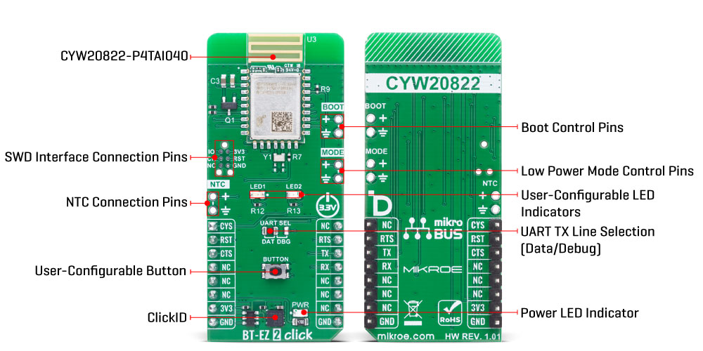
BT-EZ 2 Click is a compact add-on board that provides Bluetooth Low Energy connectivity, enabling developers to quickly integrate wireless communication into embedded systems. It is based on the CYW20822-P4TAI040, a fully integrated Bluetooth Low Energy 5.0 module from Infineon that combines the CYW20822 silicon device with onboard crystal oscillator, passive components, embedded flash memory, and an integrated trace antenna. Pre-loaded with EZ-Serial firmware, the module offers an easy-to-use command interface, 1MB of embedded flash with over-the-air update support, a 16MHz Arm Cortex-M0 MCU, and radio operation supporting 2Mbps, 1Mbps, 500kbps, and 125kbps data rates with TX output power up to +4dBm and RX sensitivity down to –101dBm. BT-EZ 2 Click is ideal for wearables, smart home systems, IoT nodes, healthcare devices, and industrial applications where robust, low-power Bluetooth connectivity is required.
BT-EZ 2 Click is fully compatible with the mikroBUS™ socket and can be used on any host system supporting the mikroBUS™ standard. It comes with the mikroSDK open-source libraries, offering unparalleled flexibility for evaluation and customization. What sets this Click board™ apart is the groundbreaking ClickID feature, enabling your host system to automatically detect and identify this add-on board.
This product is no longer in stock
Availability date:
OFF
| Company | Stock | Price |
|---|---|---|
BT-EZ 2 Click is based on the CYW20822-P4TAI040, a fully integrated Bluetooth Low Energy wireless module from Infineon that combines the CYW20822 silicon device with onboard crystal oscillator, passive components, embedded flash memory, and an integrated trace antenna. This module is pre-loaded with EZ-Serial firmware, offering a user-friendly command interface for configuration and use, and is fully qualified by the Bluetooth SIG as a cost-optimized Bluetooth 5.0 solution suitable for a wide range of embedded applications. With 1MB of embedded flash memory, the module supports non-volatile storage for self-sufficient operation and over-the-air firmware updates, ensuring flexibility and long-term adaptability.
The integrated 16MHz Arm Cortex-M0 microcontroller enables efficient performance, while the radio supports multiple Bluetooth Low Energy data rates, including 2Mbps, 1Mbps, 500kbps, and 125kbps, giving developers scalability for different use cases. The module delivers a maximum transmit output power of +4dBm and achieves a connection range of up to 250 meters in ideal line-of-sight conditions, while the receiver offers high sensitivity of –101dBm at 125kbps, ensuring robust communication even in challenging environments. These capabilities make BT-EZ 2 Click an excellent solution for wearable devices, smart home systems, IoT nodes, healthcare monitoring, and industrial applications where dependable Bluetooth connectivity, low power consumption, and simple integration are required.
This Click board™ establishes communication between the CYW20822-P4TAI040 module and the host MCU through a UART interface, using standard UART RX and TX pins and hardware flow control via CTS and RTS pins. The default communication speed is set at 115200bps, ensuring efficient data exchange. The board also features a UART SEL jumper that allows the selection of the UART TX signal purpose, enabling it to function either as a standard UART TX signal for data exchange or as a UART TX debug signal, with the mode determined by placing the jumper in the DAT or DBG position. In addition to the interface pins, the board features a reset (RST) pin for hard-resetting the module when necessary, CYS pin for choosing between Command/Data mode (HIGH for command, LOW for data), and SWD pads designed for use with MIKROE's 6-pin Needle Cable, providing an optional flash and debug SWD (Serial Wire Debug) interface functionality.
BT-EZ 2 Click also provides additional user-configurable features and control options, three unpopulated 2-pin headers to enhance flexibility and ease of use in different application scenarios. The NTC header is intended for connecting an external Negative Temperature Coefficient thermistor, which allows developers to implement temperature-dependent control or monitoring, although its specific role depends on the intended application. The MODE header is used for low-power mode control, enabling the module to be configured for reduced energy consumption. The BOOT header provides access to boot control functionality, allowing the user to manage firmware loading or recovery processes as required during development or field updates.
In addition to these headers, the board features user-friendly elements such as a BUTTON switch for triggering custom-defined actions or module commands, as well as two LED indicators, a red LED (LED1) and a yellow LED (LED2), which can be used to provide status feedback, signal communication activity, or serve as general-purpose indicators during prototyping and debugging.
This Click board™ can be operated only with a 3.3V logic voltage level. The board must perform appropriate logic voltage level conversion before using MCUs with different logic levels. It also comes equipped with a library containing functions and example code that can be used as a reference for further development.
Type
BT/BLE
Applications
Ideal for wearables, smart home systems, IoT nodes, healthcare devices, and industrial applications
On-board modules
CYW20822-P4TAI040 - Bluetooth® low energy module from Infineon
Key Features
Bluetooth Low Energy 5.0 module with integrated trace antenna, onboard 1MB embedded flash memory with support for non-volatile storage and over-the-air firmware updates, pre-loaded EZ-Serial firmware providing an intuitive command interface, a 16MHz Arm Cortex-M0 microcontroller for processing, multi-rate Bluetooth operation, high receiver sensitivity, UART communication with hardware flow control, and more
Interface
UART
Feature
ClickID
Compatibility
mikroBUS™
Click board size
L (57.15 x 25.4 mm)
Input Voltage
3.3V
This table shows how the pinout on BT-EZ 2 Click corresponds to the pinout on the mikroBUS™ socket (the latter shown in the two middle columns).
| Notes | Pin | Pin | Notes | ||||
|---|---|---|---|---|---|---|---|
| Command/Data Mode Control | CYS | 1 | AN | PWM | 16 | NC | |
| Reset / ID SEL | RST | 2 | RST | INT | 15 | RTS | UART RTS |
| UART CTS / ID COMM | CTS | 3 | CS | RX | 14 | TX | UART TX |
| NC | 4 | SCK | TX | 13 | RX | UART RX | |
| NC | 5 | MISO | SCL | 12 | NC | ||
| NC | 6 | MOSI | SDA | 11 | NC | ||
| Power Supply | 3.3V | 7 | 3.3V | 5V | 10 | NC | |
| Ground | GND | 8 | GND | GND | 9 | GND | Ground |
| Label | Name | Default | Description |
|---|---|---|---|
| LD1 | PWR | - | Power LED Indicator |
| LD2-LD3 | LED1-LED2 | - | User-Configurable LED Indicators |
| JP1 | UART SEL | Left | UART TX Line Selection DAT/DBG: Left position DAT, Right position DBG |
| T1 | BUTTON | - | User-Configurable Button |
| Description | Min | Typ | Max | Unit |
|---|---|---|---|---|
| Supply Voltage | - | 3.3 | - | V |
| Frequency Range | 2.402 | - | 2.480 | GHz |
| TX Output Power | - | - | +4 | dBm |
| RX Sensitivity | - | -101 | - | dBm |
| Line-of-sight Range (+4dBm) | - | - | 250 | m |
| Data Rates | 0.125 | - | 2 | Mbps |
BT-EZ 2 Click demo application is developed using the NECTO Studio, ensuring compatibility with mikroSDK's open-source libraries and tools. Designed for plug-and-play implementation and testing, the demo is fully compatible with all development, starter, and mikromedia boards featuring a mikroBUS™ socket.
Example Description
This example demonstrates the use of BT-EZ 2 Click board by processing data from a connected BLE device.
Key Functions
btez2_cfg_setup This function initializes Click configuration structure to initial values.btez2_init This function initializes all necessary pins and peripherals used for this Click board.btez2_cmd_action This function sends a specified action command to the Click module.btez2_cmd_set This function sends a specified set command to the Click module.btez2_read_packet This function reads a response or event packet from the Click module and stores it in ctx->evt_pkt structure.Application Init
Initializes the driver and logger.
Application Task
Application task is split in few stages:
Powers up the device and checks the communication.
Restores factory settings and reads the BT address and name.
Performs a BT terminal example by processing all data from a connected BLE device and sending back an adequate response messages.
Application Output
This Click board can be interfaced and monitored in two ways:
Additional Notes and Information
The complete application code and a ready-to-use project are available through the NECTO Studio Package Manager for direct installation in the NECTO Studio. The application code can also be found on the MIKROE GitHub account.
NOTE: Please be advised that any peripheral devices or accessories shown connected to the Click board™ are not included in the package. Check their availability in our shop or in the YMAN section below.

$50.00

$889.00

$95.00

$549.00

$299.00

$29.00

$29.00

$6.59

$3.60

$119.00

$449.00

$349.00

$349.00

$349.00

$299.00

$269.00

$249.00

$209.00
