


OFF
GO LOCAL
| Company | Stock | Price |
|---|---|---|


MIKROE-4192
20 g
Status:
XSENS MTi-3 Click is a compact add-on board that contains a fully functional module that can be configured as an Inertial Measurement Unit, Vertical reference Unit, or even an Attitude & Heading Reference System. This board features the MTi-3-5A, a module outputting 3D orientation, 3D rate of turn, 3D accelerations, and 3D magnetic field, depending on the product configuration from Xsens. The industry-standard communication protocol such as UART, SPI, or I2C allows for customization of the data message in terms of data, frequency, and output format. With a roll/pitch accuracy of 0.8º RMS and yaw accuracy of 2º RMS under dynamic conditions, the output of this Click board™ is an excellent choice for control and stabilization of any object and navigation of miniature aerial vehicles, mobile robots or robotics-on-the-move in general, or industrial-grade VR/AR, HMD’s and handheld devices.
XSENS MTi-3 Click is supported by a mikroSDK compliant library, which includes functions that simplify software development. This Click board™ comes as a fully tested product, ready to be used on a system equipped with the mikroBUS™ socket.
This product is no longer in stock
Availability date:
OFF
| Company | Stock | Price |
|---|---|---|
XSENS MTi-3 Click is based on the MTi-3-5A, a self-contained Attitude Heading and Reference System (AHRS), Vertical Reference Unit (VRU), and Inertial Measurement Unit (IMU) module from Xsens. The MTi-3-5A module supports all features of the MTi-1 series, features a 3D accelerometer, a 3D gyroscope, a high-accuracy crystal, a low-power MCU, and it is also a full magnetometer-enhanced AHRS. It can output 3D orientation data, free acceleration, and calibrated sensors data (rate of turn, magnetic field). The MTi-3-5A is easily configurable for the outputs, depends on the application needs, and can be set to use one of the filter profiles available within the Xsens sensor fusion engine. In this way, the MTi-3-5A module limits the load and the power consumption on the user application processor.
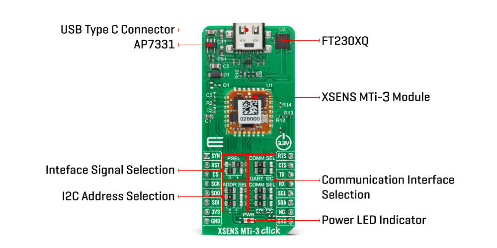
This Click board™ is equipped with the USB type C connector. It allows the module to be powered and configured by a personal computer (PC) using FT230X, a highly integrated USB to UART bridge solution from FTDI which has been designed to operate efficiently with USB host controllers by using as little bandwidth as possible when compared to the total USB bandwidth available. This module that can also be configured easily by the free downloadable Xsens MT Software Suite as an Inertial Measurement Unit (IMU), Vertical reference Unit (VRU), or even an Attitude & Heading Reference System (AHRS), which is applying Xsens’ powerful Kalman filtering XKF3 Core.
The XSENS MTi-3 Click has 2 power supply pins. The first pin represents the main power supply of the module powered via a low dropout linear regulator AP7331 from Diodes Incorporated that receives a 5V power supply from USB to UART solution and gives 3.3V on its output that is used as the main power supply of the module. The second pin represents the digital supply voltage and is powered by 3.3V directly from the mikroBUS™ socket.
This Click board™ communicates with MCU using the UART interface as its default communication interface but also has the possibility for the user to use other interfaces such as SPI and I2C if he wants to configure the module and write the library by himself. The desired interface selection can be performed through the peripheral selection pins by positioning SMD jumpers labeled as PSEL to an appropriate position. The module reads the state of these pins at Start-Up and configures its peripheral interface. To change the selected interface, the logic levels of those pins must be set first, and then the module needs to be reset.
The selection between UART/I2C and SPI/I2C interfaces can be performed by positioning SMD jumpers labeled as COMM SEL to an appropriate position. The user can also configure the I2C slave address through the ADD0, ADD1, and ADD2 pins by positioning SMD jumpers labeled as ADDR SEL to an appropriate position. Note that all the jumpers must be placed to the same side, or else the Click board™ may become unresponsive.
Additional functionality routed at RST and AN pins of the mikroBUS™ socket give the user the ability to use the reset function and to receive the latest available data message. Also, this Click board™ has two pins INT and PWM pins that can be used in many ways. For example, it can be used as serial UART connections CTS and RTS in UART full-duplex mode or can be used as RX/TX control signals in UART half-duplex mode. Regardless of these functions, the INT pin can also be used as a classic interrupt function.
This Click board™ is designed to be operated only with a 3.3V logic voltage level. A proper logic voltage level conversion should be performed before the Click board™ is used with MCUs with different logic levels.
Type
Magnetic,Motion
Applications
Ideal for control and stabilization of any object and navigation like miniature aerial vehicles, robotics, or industrial-grade VR/AR, HMD’s and handheld devices
On-board modules
MTi-3-5A - Attitude Heading and Reference System (AHRS), Vertical Reference Unit (VRU), and Inertial Measurement Unit (IMU) module from Xsens
Key Features
Full-featured AHRS module, uniform interface over product lifetime, always best-in-class inertial sensors incorporated, low power consumption, industry-standard communication protocols supported, and more
Interface
I2C,SPI,UART,USB
Feature
No ClickID
Compatibility
mikroBUS™
Click board size
L (57.15 x 25.4 mm)
Input Voltage
3.3V
This table shows how the pinout on XSENS MTi-3 Click corresponds to the pinout on the mikroBUS™ socket (the latter shown in the two middle columns).
| Notes | Pin | Pin | Notes | ||||
|---|---|---|---|---|---|---|---|
| Sync Interface | SYN | 1 | AN | PWM | 16 | RTS | UART TX CTRL Signal UART RTS |
| Reset | RST | 2 | RST | INT | 15 | CTS | Data Ready Output UART RX CTRL Signal UART CTS |
| SPI Chip Select | CS | 3 | CS | RX | 14 | TX | UART TX |
| SPI Clock | SCK | 4 | SCK | TX | 13 | RX | UART RX |
| SPI Data OUT | SDO | 5 | MISO | SCL | 12 | SCL | I2C Clock |
| SPI Data IN | SDI | 6 | MOSI | SDA | 11 | SDA | I2C Data |
| Power Supply | 3.3V | 7 | 3.3V | 5V | 10 | NC | |
| Ground | GND | 8 | GND | GND | 9 | GND | Ground |
| Label | Name | Default | Description |
|---|---|---|---|
| LD1 | PWR | - | Power LED Indicator |
| JP1-JP2 | PSEL | Left | Interface Signal Selection: Left position 0, Right position 1 |
| JP3-JP4 | COMM SEL | Left | Communication Interface Selection: Left position UART, Right position I2C |
| JP5-JP7 | COMM SEL | Left | Communication Interface Selection: Left position SPI, Right position I2C |
| JP8-JP10 | ADDR SEL | Left | I2C Address Selection: Left position 0, Right position 1 |
| Description | Min | Typ | Max | Unit |
|---|---|---|---|---|
| Supply Voltage | - | 3.3 | - | V |
| Gyroscope Range | -2000 | - | +2000 | deg/s |
| Accelerometer Range | -16 | - | +16 | g |
| Magnetometer Range | - | - | 8 | G |
We provide a library for the XSENS MTi-3 Click as well as a demo application (example), developed using MIKROE compilers. The demo can run on all the main MIKROE development boards.
Package can be downloaded/installed directly from NECTO Studio Package Manager (recommended), downloaded from our LibStock™ or found on MIKROE github account.
Library Description
This library contains API for XSENS MTi-3 Click driver.
Key functions
xsensmti3_parser XSENS MTi-3 general parser.
xsensmti3_get_data XSENS MTi-3 get Roll, Pitch and Yaw.
xsensmti3_check_package XSENS MTi-3 checks package.
Example Description
This example reads and processes data from XSENS MTi-3 clicks.
void application_task ( void )
{
uint8_t check_data = 0;
uint8_t cnt = 0;
xsensmti3_process( );
// STARTS COLLECTING DATA
if ( active_flag == XSENSMTI3_WAIT_FOR_START )
{
memset( ¤t_parser_buf[ 0 ], 0 , PROCESS_PARSER_BUFFER_SIZE );
parser_buf_cnt = 0;
active_flag = 0;
start_rsp = 0;
rsp_cnt = 0;
active_flag = XSENSMTI3_START_PROCESS;
}
if ( ( parser_buf_cnt > 100 ) && ( active_flag == XSENSMTI3_START_PROCESS ) )
{
active_flag = XSENSMTI3_DATA_PROCESSING;
}
if ( active_flag == XSENSMTI3_DATA_PROCESSING )
{
check_data = xsensmti3_check_package( ¤t_parser_buf[ 0 ], &start_rsp );
if ( check_data == XSENSMTI3_OK )
{
active_flag = XSENSMTI3_PARSER_DATA;
}
else
{
active_flag = XSENSMTI3_WAIT_FOR_START;
}
}
if ( active_flag == XSENSMTI3_PARSER_DATA )
{
xsensmti3_parser( ¤t_parser_buf[ 0 ], start_rsp, &parse_data_obj );
log_printf( &logger, ">> Quaternion data <<rn" );
for ( cnt = 0; cnt < 4; cnt++ )
{
log_printf( &logger, ">> Q: %frn", parse_data_obj.quat_obj.quat_data[ cnt ] );
}
log_printf( &logger, "--------------rn" );
xsensmti3_get_data( &parse_data_obj.quat_obj, &data_obj );
log_printf( &logger, ">> ROLL: %.4f rn", data_obj.roll );
log_printf( &logger, ">> PITCH: %.4f rn", data_obj.pitch );
log_printf( &logger, ">> YAW: %.4f rn", data_obj.yaw );
active_flag = XSENSMTI3_WAIT_FOR_START;
log_printf( &logger, "--------------rn" );
}
}
The full application code, and ready to use projects can be installed directly from NECTO Studio Package Manager (recommended), downloaded from our LibStock™ or found on MIKROE github account.
Other MIKROE Libraries used in the example:
Additional notes and informations
Depending on the development board you are using, you may need USB UART click, USB UART 2 Click or RS232 Click to connect to your PC, for development systems with no UART to USB interface available on the board. UART terminal is available in all MIKROE compilers.
This Click board™ is supported with mikroSDK - MIKROE Software Development Kit. To ensure proper operation of mikroSDK compliant Click board™ demo applications, mikroSDK should be downloaded from the LibStock and installed for the compiler you are using.
For more information about mikroSDK, visit the official page.
NOTE: Please be advised that any peripheral devices or accessories shown connected to the Click board™ are not included in the package. Check their availability in our shop or in the YMAN section below.

$95.00

$889.00

$549.00

$299.00

$29.00

$29.00

$3.30

$3.60

$119.00

$449.00

$349.00

$349.00

$349.00

$299.00

$269.00

$249.00

$209.00
