


OFF
GO LOCAL
| Company | Stock | Price |
|---|---|---|


MIKROE-1937
32 g
Status:
WiFly Click is a compact add-on board that allows you to connect your host microcontroller to 802.11b/g/n wireless networks. This board features the RN-131, a standalone embedded wireless 802.11b/g/n networking module from Microchip. The WiFly module incorporates a 2.4GHz radio, processor, TCP/IP stack, real-time clock, crypto accelerator, and power management. It can wake up, connect to a wireless network, send data, and return to sleep in less than 100 milliseconds, allowing this Click board™ to run for years with low power consumption. This Click board™ makes the perfect solution for IoT, data logging, telemetry, remote equipment monitoring, or mobile wireless applications such as asset monitoring, GPS tracking, battery sensors, and more.
WiFly Click is supported by a mikroSDK compliant library, which includes functions that simplify software development. This Click board™ comes as a fully tested product, ready to be used on a system equipped with the mikroBUS™ socket.
This product is no longer in stock
Availability date:
OFF
| Company | Stock | Price |
|---|---|---|
NOTE: Enhance your connectivity options with our WiFi Active FPC Antenna, designed to integrate with this Click board™ seamlessly. Unlock the true potential of wireless connectivity in your projects using this high-performance antenna, currently available in our offer.
WiFly Click is based on the RN-131, a standalone embedded wireless 802.11b/g/n networking module from Microchip. The RN-131 comes preloaded with software to simplify integration and minimize application development, controlled with simple ASCII commands for scanning, authenticating, and connecting to the WiFi networks. This Click board™ has many built-in networking applications, such as DHCP, UDP, DNS, ARP, ICMP, TCP, HTTP client, and FTP client. The module can achieve data rates of up to 54Mbps over an onboard chip antenna or external one through a u.Fl connector. Regarding security, this Click board™ features WEP-128, WPA-PSK(TKIP), or WPA2-PSK(AES) for WiFi authentications. Remote configuration can be made over WiFi using Telnet, although firmware can be upgraded over over-the-air (OtA).
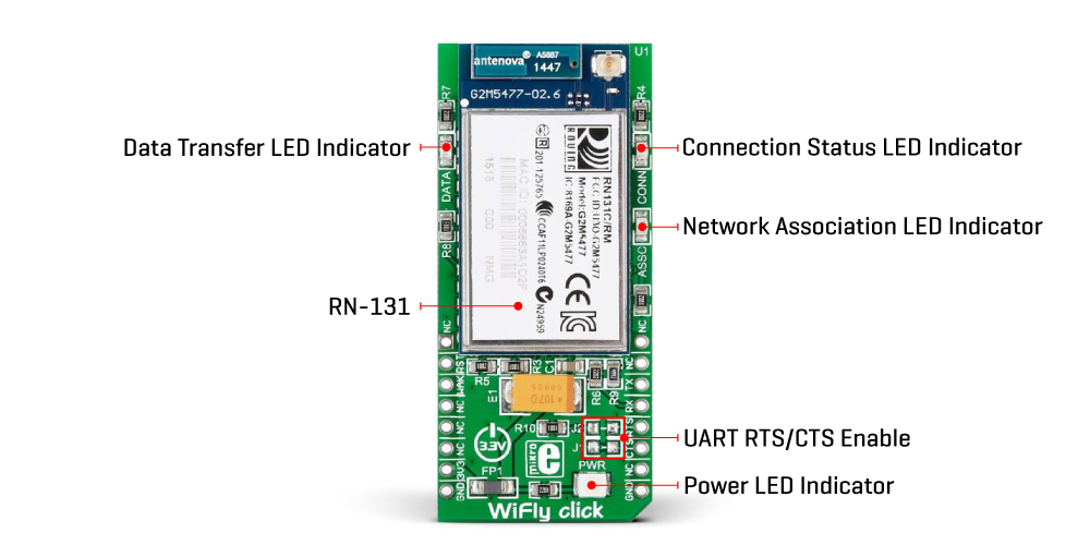
To communicate with the host MCU, the WiFly Click uses the UART interface of the mikroBUS™ socket, with commonly used UART RX and TX pins. This module can be reset over the standard RST pin of the mikroBUS™ socket. The module also supports Sleep mode and can be awakened with active high on the WAK pin (FORCE_AWAKE). UART RTS and CTS flow can be controlled over the CTS, and RTS pins as additional functionality enabled through a population of the J1 and J2 solder jumpers. This Click board™ also features LEDs for visual status presentation. Red ASSC LED shows if the module is associated with a network, with OFF status if internet access is OK. The yellow LED labeled with DATA shows when data is transferred, and the green CONN LED indicates the TCP/IP connection status with different light patterns depending on the IP and internet statuses.
This Click board™ can only be operated from a 3.3V logic voltage level. Therefore, the board must perform appropriate logic voltage conversion before using MCUs with different logic levels. However, the Click board™ comes equipped with a library containing functions and an example code that can be used as a reference for further development.
Type
WiFi
Applications
Can be used for IoT, data logging, telemetry, remote equipment monitoring, or mobile wireless applications such as asset monitoring, GPS tracking, battery sensors, and more
On-board modules
RN-131 - standalone embedded wireless 802.11b/g/n networking module from Microchip
Key Features
Qualified 2.4-GHz IEEE 802.11 b/g transceiver, onboard ceramic chip antenna plus connector for external antenna, packed with features such as DHCP, UDP, DNS, ARP, ICMP, TCP, HTTP and FTP client, authentication part features WEP-128, WPA-PSK(TKIP), or WPA2-PSK(AES), and more
Interface
GPIO,UART
Feature
No ClickID
Compatibility
mikroBUS™
Click board size
L (57.15 x 25.4 mm)
Input Voltage
3.3V
This table shows how the pinout on WiFly Click corresponds to the pinout on the mikroBUS™ socket (the latter shown in the two middle columns).
| Notes | Pin | Pin | Notes | ||||
|---|---|---|---|---|---|---|---|
| NC | 1 | AN | PWM | 16 | NC | ||
| Reset | RST | 2 | RST | INT | 15 | NC | |
| Forced Wake-Up | WAK | 3 | CS | RX | 14 | TX | UART TX |
| NC | 4 | SCK | TX | 13 | RX | UART RX | |
| NC | 5 | MISO | SCL | 12 | RTS | UART RTS | |
| NC | 6 | MOSI | SDA | 11 | CTS | UART CTS | |
| Power Supply | 3.3V | 7 | 3.3V | 5V | 10 | NC | |
| Ground | GND | 8 | GND | GND | 9 | GND | Ground |
| Label | Name | Default | Description |
|---|---|---|---|
| LD1 | PWR | - | Power LED Indicator |
| LD2 | ASSC | - | Network Association LED Indicator |
| LD3 | CONN | - | Connection Status LED Indicator |
| LD4 | DATA | - | Data Transfer LED Indicator |
| J1 | J1 | Unpopulated | UART CTS Clear-To-Send Enable Jumper |
| J2 | J2 | Unpopulated | UART RTS Ready-To-Send Enable Jumper |
| Description | Min | Typ | Max | Unit |
|---|---|---|---|---|
| Supply Voltage | - | 3.3 | - | V |
| Operating Frequency Range | 2402 | - | 2480 | MHz |
| Data Rate | 1 | - | 54 | Mbps |
| Receive Sensitivity | - | -85 | - | dBm |
| Output Power | - | +18 | - | dBm |
NOTE: Please be advised that any peripheral devices or accessories shown connected to the Click board™ are not included in the package. Check their availability in our shop or in the YMAN section below.

$889.00

$95.00

$549.00

$299.00

$29.00

$29.00

$6.59

$3.60

$119.00

$449.00

$349.00

$349.00

$349.00

$299.00

$269.00

$249.00

$209.00
