


OFF
GO LOCAL
| Company | Stock | Price |
|---|---|---|


MIKROE-5250
19 g
Status:
V to Hz 3 Click is a compact add-on board that converts an analog voltage input signal into a specific frequency pulse wave signal. This board features the AD7740, an ultrasmall synchronous voltage-to-frequency converter from Analog Devices. The AD7740 has a linear response, so applying a voltage from 3V up to 5V on its VIN terminal will generate the pulse with a frequency linearly proportional to the input voltage. It contains an integrated 2.5V bandgap reference defining the span of the VFC and can be overdriven using an external reference. The full-scale output frequency is synchronous with the input clock signal provided by the LTC6903 programmable oscillator, with a maximum input frequency of 1MHz. Based on the analog input value, the output frequency goes from 10% to 90% of the input frequency. This Click board™ is the most suitable for low-cost analog-to-digital conversion, linear frequency modulation, voltage-to-frequency conversion, and as a variable clock signal generator.
V to Hz 3 Click is supported by a mikroSDK compliant library, which includes functions that simplify software development. This Click board™ comes as a fully tested product, ready to be used on a system equipped with the mikroBUS™ socket.
This product is no longer in stock
Availability date:
OFF
| Company | Stock | Price |
|---|---|---|
V to Hz 3 Click as its foundation uses the AD7740, a CMOS synchronous Voltage-to-Frequency Converter (VFC), which uses a charge-balanced conversion technique from Analog Devices. The input voltage signal from 0V up to 5V from its VIN terminal is applied to a proprietary front-end based around an analog modulator that converts the input voltage into an output pulse train. Depending on the analog input value, the output frequency goes from 10% to 90% of the input frequency provided by the SPI-configurable LTC6903 programmable oscillator, with a maximum input frequency of 1MHz.
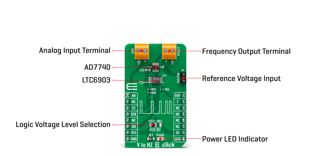
The analog input signal to the AD7740 is continuously sampled by a switched capacitor modulator whose sampling rate is set by a master clock (primary input frequency of the AD7740). The input signal may also be buffered, setting the BUF pin of the mikroBUS™ socket to a high logic state before being applied to the sampling capacitor of the modulator, isolating the sampling capacitor charging currents from the analog input pin. The AD7740 also contains an on-chip 2.5 V default bandgap reference, the reference input to the core of the AD7740 defining the span of the VFC. Alternatively, an external reference may be used to overdrive the internal reference by applying it to an onboard header marked as REFIN.
Alongside SPI communication, this Click board™ also uses several additional pins. The BUF pin mentioned above represents the Buffered mode selection, while the AN pin indicates the presence of an external analog signal. The last of the enabled pins is the F signal, routed to the INT pin of the mikroBUS™ socket, which can also serve as output frequency from the AD7740 in the same way as the FOUT terminal.
This Click board™ can operate with both 3.3V and 5V logic voltage levels selected via the VCC SEL jumper. This way, it is allowed for both 3.3V and 5V capable MCUs to use the communication lines properly. However, the Click board™ comes equipped with a library containing easy-to-use functions and an example code that can be used, as a reference, for further development.
Type
Measurements
Applications
Can be used for low-cost analog-to-digital conversion, linear frequency modulation, voltage-to-frequency conversion, and as a variable clock signal generator
On-board modules
AD7740 - voltage-to-frequency converter from Analog Devices
LTC6903 - programmable oscillator from Analog Devices
Key Features
Synchronous operation, output frequency provided by programmable oscillator, low power consumption, internal 2.5V reference, 1MHz maximum input frequency, selectable high impedance buffered input, and more
Interface
SPI
Feature
No ClickID
Compatibility
mikroBUS™
Click board size
M (42.9 x 25.4 mm)
Input Voltage
3.3V or 5V,External
This table shows how the pinout on V to Hz 3 Click corresponds to the pinout on the mikroBUS™ socket (the latter shown in the two middle columns).
| Notes | Pin | Pin | Notes | ||||
|---|---|---|---|---|---|---|---|
| Analog Input Indicator | AN | 1 | AN | PWM | 16 | BUF | Buffered Mode |
| NC | 2 | RST | INT | 15 | F | AD7740 Frequency | |
| SPI Chip Select | CS | 3 | CS | RX | 14 | NC | |
| SPI Clock | SCK | 4 | SCK | TX | 13 | NC | |
| SPI Data OUT | SDO | 5 | MISO | SCL | 12 | NC | |
| SPI Data IN | SDI | 6 | MOSI | SDA | 11 | NC | |
| Power Supply | 3.3V | 7 | 3.3V | 5V | 10 | 5V | Power Supply |
| Ground | GND | 8 | GND | GND | 9 | GND | Ground |
| Label | Name | Default | Description |
|---|---|---|---|
| LD1 | PWR | - | Power LED Indicator |
| JP1 | VCC SEL | Left | Logic Level Voltage Selection 3V3/5V: Left position 3V3, Right position 5V |
| J1 | REFIN | Populated | External Reference Voltage Connection |
| Description | Min | Typ | Max | Unit |
|---|---|---|---|---|
| Supply Voltage | 3.3 | - | 5 | V |
| Analog Input Range VIN | 0 | - | 5 | V |
| Output Frequency Range FOUT | - | - | 1 | MHz |
| Operating Temperature Range | -40 | +25 | +105 | °C |
We provide a library for the V to Hz 3 Click as well as a demo application (example), developed using MikroElektronika compilers. The demo can run on all the main MikroElektronika development boards.
Package can be downloaded/installed directly from NECTO Studio Package Manager(recommended way), downloaded from our LibStock™ or found on Mikroe github account.
Library Description
This library contains API for V to Hz 3 Click driver.
Key functions
vtohz3_set_input_frequency This function enables and sets output frequency of the programmable oscillator, which is the AD7740 input frequency.
vtohz3_read_an_pin_voltage This function reads results of AD conversion of the AN pin and converts them to proportional voltage level.
vtohz3_get_frequency This function converts voltage to the estimated output frequency in Hz.
Example Description
This example demonstrates the use of the V to Hz 3 Click board™ by calculating the estimated output frequency from the input voltage.
 void application_task ( void )
 {
     float voltage;
     if ( VTOHZ3_OK == vtohz3_read_an_pin_voltage ( &vtohz3, &voltage ) )
     {
         log_printf( &logger, " Voltage : %.2f Vrn", voltage );
         log_printf( &logger, " Output frequency : %lu Hzrnn",
                     vtohz3_get_frequency ( &vtohz3, voltage, VTOHZ3_VREF_INTERNAL_2V5 ) );
     }
     Delay_ms( 1000 );
 }
The full application code, and ready to use projects can be installed directly from NECTO Studio Package Manager(recommended way), downloaded from our LibStock™ or found on Mikroe github account.
Other Mikroe Libraries used in the example:
Additional notes and informations
Depending on the development board you are using, you may need USB UART click, USB UART 2 Click or RS232 Click to connect to your PC, for development systems with no UART to USB interface available on the board. UART terminal is available in all MikroElektronika compilers.
This Click board™ is supported with mikroSDK - MikroElektronika Software Development Kit. To ensure proper operation of mikroSDK compliant Click board™ demo applications, mikroSDK should be downloaded from the LibStock and installed for the compiler you are using.
For more information about mikroSDK, visit the official page.
NOTE: Please be advised that any peripheral devices or accessories shown connected to the Click board™ are not included in the package. Check their availability in our shop or in the YMAN section below.

$889.00

$95.00

$549.00

$299.00

$29.00

$29.00

$6.59

$3.60

$119.00

$449.00

$349.00

$349.00

$349.00

$299.00

$269.00

$249.00

$209.00
