


OFF
GO LOCAL
| Company | Stock | Price |
|---|---|---|


MIKROE-6789
20 g
Status:
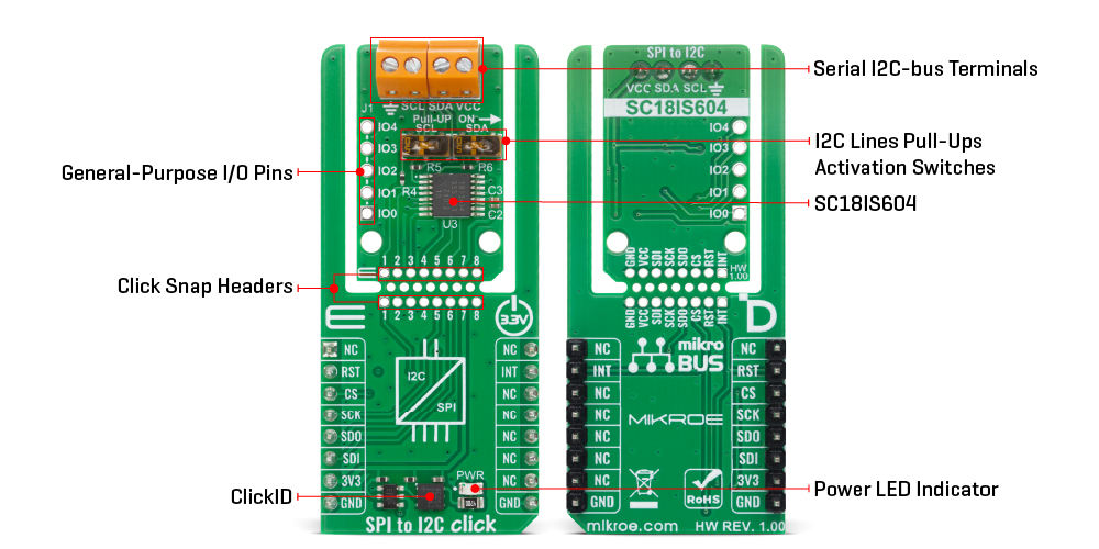
SPI to I2C Click is a compact add-on board that enables communication between SPI and I2C interfaces, allowing a host microcontroller to control multiple I2C peripherals even without native I2C support. It is based on the SC18IS604, an SPI-to-I2C bridge from NXP, which manages all I2C-bus operations including protocol handling, arbitration, and timing to ensure reliable data transfer. The board operates as an SPI slave supporting Mode 3 and provides a single I2C controller channel, integrating five GPIO pins, 255-byte transmit and receive buffers, and support for SPI speeds up to 1.2MHz and I2C Fast-mode up to 375kHz. It also features Deep Power-Down mode with CS wake-up, interrupt and reset pins, and onboard pull-up switches for easy configuration. SPI to I2C Click is ideal for embedded applications requiring protocol bridging, such as connecting sensors, memory devices, or peripheral modules in mixed-interface systems.
SPI to I2C Click is fully compatible with the mikroBUS™ socket and can be used on any host system supporting the mikroBUS™ standard. It comes with the mikroSDK open-source libraries, offering unparalleled flexibility for evaluation and customization. What sets this Click board™ apart is the groundbreaking ClickID feature, enabling your host system to automatically detect and identify this add-on board, alongside a Click Snap feature introducing a new level of flexibility and ease of use.
This product is no longer in stock
Availability date:
OFF
| Company | Stock | Price |
|---|---|---|
SPI to I2C Click is based on the SC18IS604, an SPI-to-I2C bridge from NXP that functions as an interface between the SPI bus of a host microcontroller or microprocessor and a serial I2C bus, allowing the host to directly control multiple I2C peripherals without requiring native I2C hardware support. Acting as an I2C-bus controller, the SC18IS604 manages all bus-specific operations, including protocol handling, arbitration, and timing, ensuring reliable and synchronized data transfer between the two communication standards. The module operates as an SPI slave device, supporting SPI Mode 3, and provides a single primary I2C-bus controller channel for communication with I2C devices. SPI to I2C Click is ideal for embedded applications that require bridging between SPI and I2C communication domains, such as integrating sensors, memory modules, and peripheral controllers in systems where only one of the two interfaces is natively supported.
This Click board™ is designed in a unique format supporting the newly introduced MIKROE feature called "Click Snap." Unlike the standardized version of Click boards, this feature allows the main sensor/IC/module area to become movable by breaking the PCB, opening many new possibilities for implementation. Thanks to the Snap feature, the SC18IS604 can operate autonomously by accessing its signals directly on the pins marked 1-8. Additionally, the Snap part includes a specified and fixed screw hole position, enabling users to secure the Snap board in their desired location.
The SC18IS604 integrates five general-purpose input/output (GPIO) pins accessible through an unpopulated J1 header, which can be used for custom digital control or status monitoring applications. The board’s I/O pins are 5V tolerant, enabling flexible integration with a wide range of microcontrollers. Supporting high-speed SPI communication up to 1.2MHz and I2C Fast-mode operation up to 375kHz, SPI to I2C Click ensures efficient data throughput in mixed-interface embedded systems. It incorporates 255-byte transmit and receive buffers to handle large data transactions and includes a Deep Power-Down mode with SPI Chip Select (CS) wake-up functionality for low-power applications. An internal oscillator eliminates the need for an external clock source, simplifying the design process.
The board also provides an active LOW interrupt output on the INT pin, which alerts the host MCU when the SC18IS604 requires service, and an active LOW reset pin (RST) that restores internal registers to default states and resets the I2C and SPI hardware. Additionally, the board features two pull-up enable switches that conveniently activate onboard pull-up resistors on the I2C signal lines, making configuration straightforward.
This Click board™ can be operated only with a 3.3V logic voltage level. The board must perform appropriate logic voltage level conversion before using MCUs with different logic levels. It also comes equipped with a library containing functions and example code that can be used as a reference for further development.
Click Snap is an innovative feature of our standardized Click add-on boards, designed to bring greater flexibility and optimize your prototypes. By simply snapping the PCB along predefined lines, you can easily detach the main sensor/IC/module area, reducing the overall size, weight, and power consumption - ideal for the final phase of prototyping. For more details about Click Snap, visit the official page dedicated to this feature.
Type
SPI
Applications
Ideal for embedded applications requiring protocol bridging, such as connecting sensors, memory devices, or peripheral modules in mixed-interface systems
On-board modules
SC18IS604 - SPI to I2C-bus bridge from NXP
Key Features
Single primary I2C-bus controller channel, five general-purpose input/output pins, 5V tolerant I/O pins, support for high-speed SPI communication and I2C Fast-mode operation, 255-byte transmit and receive buffers, Deep Power-Down mode with SPI Chip Select wake-up functionality, an internal oscillator for clock generation, Click Snap design support, and more
Interface
GPIO,I2C,SPI
Feature
Click Snap,ClickID
Compatibility
mikroBUS™
Click board size
L (57.15 x 25.4 mm)
Input Voltage
3.3V
This table shows how the pinout on SPI to I2C Click corresponds to the pinout on the mikroBUS™ socket (the latter shown in the two middle columns).
| Notes | Pin | Pin | Notes | ||||
|---|---|---|---|---|---|---|---|
| NC | 1 | AN | PWM | 16 | NC | ||
| Reset / ID SEL | RST | 2 | RST | INT | 15 | INT | Interrupt |
| SPI Select / ID COMM | CS | 3 | CS | RX | 14 | NC | |
| SPI Clock | SCK | 4 | SCK | TX | 13 | NC | |
| SPI Data OUT | SDO | 5 | MISO | SCL | 12 | NC | |
| SPI Data IN | SDI | 6 | MOSI | SDA | 11 | NC | |
| Power Supply | 3.3V | 7 | 3.3V | 5V | 10 | NC | |
| Ground | GND | 8 | GND | GND | 9 | GND | Ground |
| Label | Name | Default | Description |
|---|---|---|---|
| LD1 | PWR | - | Power LED Indicator |
| SW1-SW2 | Pull-UP ON | Right | I2C Lines Pull-Ups Activation Switches |
| Description | Min | Typ | Max | Unit |
|---|---|---|---|---|
| Supply Voltage | - | 3.3 | - | V |
| SPI Clock Frequency | - | - | 1.2 | MHz |
| I2C Clock Frequency | - | - | 375 | kHz |
| GPIO Voltage Tolerance | - | 5 | - | V |
| TX/RX Buffer Size | - | 255 | - | bytes |
SPI to I2C Click demo application is developed using the NECTO Studio, ensuring compatibility with mikroSDK's open-source libraries and tools. Designed for plug-and-play implementation and testing, the demo is fully compatible with all development, starter, and mikromedia boards featuring a mikroBUS™ socket.
Example Description
This example demonstrates the use of SPI to I2C Click board by reading the manufacturer ID of a 3D Hall 11 Click board connected to the I2C port and controlling the GPIO pins.
Key Functions
spitoi2c_cfg_setup Config Object Initialization function.spitoi2c_init Initialization function.spitoi2c_default_cfg Click Default Configuration function.spitoi2c_i2c_read_after_write This function performs a write then read with a repeated start to the I2C target device.spitoi2c_gpio_write This function writes a desired data to the gpio port.spitoi2c_gpio_read This function reads data from the gpio port.Application Init
Initializes the driver and performs the Click default config which enables the device and sets the GPIO pins 0-2 as push-pull output and others as input. Then sets the I2C clock to 99KHz, I2C address to 127 and disables I2C timeout. After that, reads and displays the chip firmware version.
Application Task
Reads the manufacturer ID of a 3D Hall 11 Click board connected to the I2C port, toggles the output pins and displays the GPIO port state. The results will be displayed on the USB UART approximately once per second.
Application Output
This Click board can be interfaced and monitored in two ways:
Additional Notes and Information
The complete application code and a ready-to-use project are available through the NECTO Studio Package Manager for direct installation in the NECTO Studio. The application code can also be found on the MIKROE GitHub account.
NOTE: Please be advised that any peripheral devices or accessories shown connected to the Click board™ are not included in the package. Check their availability in our shop or in the YMAN section below.

$1.20

$1.20

$1.74

$3.00

$889.00

$95.00

$549.00

$299.00

$29.00

$29.00

$6.59

$3.60

$119.00

$449.00

$349.00

$349.00

$349.00

$299.00

$269.00

$249.00

$209.00
