


OFF
GO LOCAL
| Company | Stock | Price |
|---|---|---|


EtherCAT Click
MIKROE-6619
20 g
Status:
SolidSwitch 9 Click is a compact add-on board designed for high-side switching across four independent channels for controlling resistive and inductive loads directly connected to ground, ideal for use in automotive and industrial environments. It is based on the VN9D5D20FN, a 4-channel high-side driver from STMicroelectronics with 24-bit SPI control for programming, diagnostics, and real-time control, integrated 10-bit ADC for precise current sensing, and flexible output control. It includes built-in diagnostics, it integrates a PWM engine with independent phase and frequency control for each channel, and supports multiple operating modes including limp-home functionality. SolidSwitch 9 Click is well suited for applications such as automotive lighting, motor control, industrial automation, and any system requiring safe, intelligent high-side load switching.
SolidSwitch 9 Click is fully compatible with the mikroBUS™ socket and can be used on any host system supporting the mikroBUS™ standard. It comes with the mikroSDK open-source libraries, offering unparalleled flexibility for evaluation and customization. What sets this Click board™ apart is the groundbreaking ClickID feature, enabling your host system to automatically detect and identify this add-on board.
This product is no longer in stock
Availability date:
OFF
| Company | Stock | Price |
|---|---|---|
SolidSwitch 9 Click is based on the VN9D5D20FN, a 4-channel high-side driver with SPI control from STMicroelectronics, developed using advanced VIPower technology and qualified under the AEC-Q100 standard. This Click board™ provides high-side switching capabilities across four independent channels, designed to control both resistive and inductive loads directly connected to ground in automotive applications. Its compliance with the European directive 2002/95/EC ensures environmental compatibility. The core functionality is centered around a 24-bit SPI interface used for programming, diagnostics, and real-time control, offering precise digital current sensing feedback for each channel via an integrated 10-bit ADC with an accuracy of 0.1% of the full-scale range. For even more precision, trimming bits allow fine-tuning of the ADC reference current.
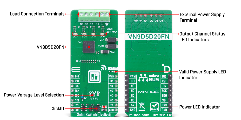
The VN9D5D20FN features four output channels (O0 to O3), which can be controlled either via the SPI interface or through two user-assignable direct inputs (DI0 and DI1), enabling flexible control even in scenarios where SPI is unavailable. Each output is accompanied by its own LED indicator (LD3 to LD6), allowing for immediate visual confirmation of the output state. To enhance safety and reliability, the VN9D5D20FN implements several diagnostic and protection mechanisms including open-load detection in the OFF-state, SPI-readable fault flags for conditions such as open-load, output short to VCC, overtemperature, communication errors, power limitations, and latch-off events.
The output current is actively limited to prevent damage during overloads, and power dissipation is regulated through dynamic thermal management, with a programmable shutdown mechanism that can either latch or auto-restart after a defined period. A dedicated VBAT LED indicator on the board provides a clear visual cue for system power availability, supporting input voltages up to 28V. The VN9D5D20FN supports multiple operation modes including Reset, Fail-safe, Normal, Standby, Sleep mode 1, Sleep mode 2, and Battery undervoltage mode, where the Reset, Fail-safe, and Sleep mode 1 are collectively referred to as limp-home mode.
In this mode, the device can function independently of the SPI interface, using VBAT and DIx signals for mode transitions and output control. By default configuration, DI0 controls outputs O0 and O1, while DI1 manages O2 and O3. Additionally, the VN9D5D20FN integrates a powerful PWM engine capable of generating independent phase-shifted PWM signals for each channel, supporting four selectable divider ratios ranging from 1/512 to 1/4096, making it ideal for finely tuned load modulation or motor control applications.
This Click board™ can operate with either 3.3V or 5V logic voltage levels selected via the VCC SEL jumper. This way, both 3.3V and 5V capable MCUs can use the communication lines properly. Also, this Click board™ comes equipped with a library containing easy-to-use functions and an example code that can be used as a reference for further development.
Type
Power Switch
Applications
Ideal for automotive lighting, motor control, industrial automation, and any system requiring safe, intelligent high-side load switching
On-board modules
VN9D5D20FN - 4-channel high-side driver with 24-bit SPI interface from STMicroelectronics
Key Features
Four independent high-side output channels, 24-bit SPI interface for programming and diagnostics, integrated 10-bit ADC with 0.1% FSR accuracy for digital current sensing, user-assignable direct input control, integrated PWM engine with independent phase and frequency control per channel, support for multiple operation modes, protection features, and more
Interface
GPIO,SPI
Feature
ClickID
Compatibility
mikroBUS™
Click board size
L (57.15 x 25.4 mm)
Input Voltage
3.3V or 5V,External
This table shows how the pinout on SolidSwitch 9 Click corresponds to the pinout on the mikroBUS™ socket (the latter shown in the two middle columns).
| Notes | Pin | Pin | Notes | ||||
|---|---|---|---|---|---|---|---|
| Output Channel Control | DI0 | 1 | AN | PWM | 16 | PWM | PWM Signal |
| ID SEL | RST | 2 | RST | INT | 15 | DI1 | Output Channel Control |
| SPI Select / ID COMM | CS | 3 | CS | RX | 14 | NC | |
| SPI Clock | SCK | 4 | SCK | TX | 13 | NC | |
| SPI Data OUT | SDO | 5 | MISO | SCL | 12 | NC | |
| SPI Data IN | SDI | 6 | MOSI | SDA | 11 | NC | |
| Power Supply | 3.3V | 7 | 3.3V | 5V | 10 | 5V | Power Supply |
| Ground | GND | 8 | GND | GND | 9 | GND | Ground |
| Label | Name | Default | Description |
|---|---|---|---|
| LD1 | PWR | - | Power LED Indicator |
| LD2 | VBAT | - | Valid Power Supply LED Indicator |
| LD3-LD6 | LD3-LD6 | - | Output Channel Status LED Indicators |
| JP1 | VCC SEL | Left | Power Voltage Level Selection 3V3/5V: Left position 3V3, Right position 5V |
| Description | Min | Typ | Max | Unit |
|---|---|---|---|---|
| Supply Voltage | 3.3 | - | 5 | V |
| External Power Supply | 4 | 13 | 28 | V |
| PWM Frequency Divider | 1/4096 | - | 1/512 | - |
SolidSwitch 9 Click demo application is developed using the NECTO Studio, ensuring compatibility with mikroSDK's open-source libraries and tools. Designed for plug-and-play implementation and testing, the demo is fully compatible with all development, starter, and mikromedia boards featuring a mikroBUS™ socket.
Example Description
This example demonstrates the use of the SolidSwitch 9 Click board by gradually increasing and decreasing the output duty cycle of each output channel one by one. After each update, the output is enabled and the diagnostic status is cleared.
Key Functions
solidswitch9_cfg_setup This function initializes Click configuration structure to initial values.solidswitch9_init This function initializes all necessary pins and peripherals used for this Click board.solidswitch9_default_cfg This function executes a default configuration of SolidSwitch 9 Click board.solidswitch9_set_out_duty This function sets the output duty cycle for the selected output channels.solidswitch9_enable_out This function enables the selected outputs.solidswitch9_clear_all_status This function clears all status registers on the SolidSwitch 9 Click board.Application Init
Initializes the logger and the Click board driver, and applies the default configuration.
Application Task
Adjusts the output duty cycle from 0% to 100% and back to 0% for each channel sequentially and clears the diagnostic status after each duty cycle update. The currently active output channel number is logged on the USB UART.
Application Output
This Click board can be interfaced and monitored in two ways:
Additional Notes and Information
The complete application code and a ready-to-use project are available through the NECTO Studio Package Manager for direct installation in the NECTO Studio. The application code can also be found on the MIKROE GitHub account.
NOTE: Please be advised that any peripheral devices or accessories shown connected to the Click board™ are not included in the package. Check their availability in our shop or in the YMAN section below.

$889.00

$95.00

$549.00

$299.00

$29.00

$29.00

$6.59

$3.60

$119.00

$449.00

$349.00

$349.00

$349.00

$299.00

$269.00

$249.00

$209.00
