


OFF
GO LOCAL
| Company | Stock | Price |
|---|---|---|


MIKROE-6767
20 g
Status:
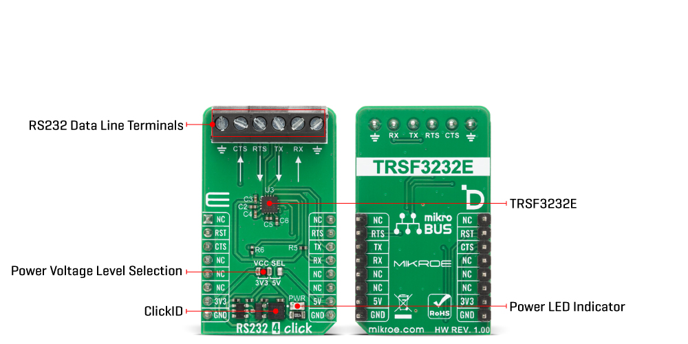
RS232 4 Click is a compact add-on board that provides a reliable RS232 interface solution for asynchronous serial communication, ensuring data exchange between microcontrollers and external serial devices. It is based on the TRSF3232E, a two-channel RS232 line driver and receiver from Texas Instruments, which integrates two drivers, two receivers, and a dual charge-pump circuit to generate the necessary RS232 voltage levels from a single supply. It features ±15kV ESD protection on all serial-port connection pins, supports data signaling rates up to 1Mbit/s, and maintains a controlled driver output slew rate of 14V/μs to 150V/μs for stable and distortion-free transmission. RS232 4 Click is ideally suited for industrial PCs, wired networking, enterprise and data center equipment, portable systems, and various handheld or battery-powered devices requiring secure and high-speed RS232 communication.
RS232 4 Click is fully compatible with the mikroBUS™ socket and can be used on any host system supporting the mikroBUS™ standard. It comes with the mikroSDK open-source libraries, offering unparalleled flexibility for evaluation and customization. What sets this Click board™ apart is the groundbreaking ClickID feature, enabling your host system to automatically detect and identify this add-on board.
This product is no longer in stock
Availability date:
OFF
| Company | Stock | Price |
|---|---|---|
RS232 4 Click is based on the TRSF3232E, a two-channel RS232 line driver and receiver from Texas Instruments, which integrates two line drivers, two line receivers, and a dual charge-pump circuit to generate the necessary RS232 voltage levels from a single supply. This Click board™ provides a reliable RS232 interface solution for asynchronous serial communication, designed to achieve robust data exchange between MCUs and external serial devices. With built-in ±15kV ESD protection on all serial-port connection pins, including ground, the device ensures high immunity to electrostatic discharges, making it suitable for use in demanding industrial and portable applications.
This Click board™ establishes communication between the TRSF3232E and the host MCU through a UART interface, using standard UART RX and TX pins and hardware flow control via CTS and RTS pins. The default communication speed is set at 115200bps, ensuring efficient data exchange. The TRSF3232E supports data signaling rates up to 1Mbit/s while maintaining a controlled driver output slew rate between 14V/μs and 150V/μs, enabling fast and reliable communication without excessive signal distortion.
The RS232 4 Click offers integration into systems where legacy or long-distance serial communication is required. This makes it an ideal solution for a wide range of use cases, including industrial PCs, wired networking, enterprise and data center equipment, battery-powered systems, handheld devices, PDAs, notebooks, and palmtop computers, where stable, high-speed, and protected RS232 communication is essential.
This Click board™ can operate with either 3.3V or 5V logic voltage levels selected via the VCC SEL jumper. This way, both 3.3V and 5V capable MCUs can use the communication lines properly. Also, this Click board™ comes equipped with a library containing easy-to-use functions and an example code that can be used as a reference for further development.
Type
RS232
Applications
Ideal for industrial PCs, wired networking, enterprise and data center equipment, portable systems, and various handheld or battery-powered devices
On-board modules
TRSF3232E - two-channel RS232 1Mbit/s line driver and receiver from Texas Instruments
Key Features
Two-channel RS232 line driver and receiver, data rates up to 1Mbit/s, controlled driver output slew rate, built-in ±15kV ESD protection, UART interface, and more
Interface
UART
Feature
ClickID
Compatibility
mikroBUS™
Click board size
M (42.9 x 25.4 mm)
Input Voltage
3.3V or 5V
This table shows how the pinout on RS232 4 Click corresponds to the pinout on the mikroBUS™ socket (the latter shown in the two middle columns).
| Notes | Pin | Pin | Notes | ||||
|---|---|---|---|---|---|---|---|
| NC | 1 | AN | PWM | 16 | NC | ||
| Reset / ID SEL | RST | 2 | RST | INT | 15 | RTS | UART RTS |
| UART CTS / ID COMM | CTS | 3 | CS | RX | 14 | TX | UART TX |
| NC | 4 | SCK | TX | 13 | RX | UART RX | |
| NC | 5 | MISO | SCL | 12 | NC | ||
| NC | 6 | MOSI | SDA | 11 | NC | ||
| Power Supply | 3.3V | 7 | 3.3V | 5V | 10 | 5V | Power Supply |
| Ground | GND | 8 | GND | GND | 9 | GND | Ground |
| Label | Name | Default | Description |
|---|---|---|---|
| LD1 | PWR | - | Power LED Indicator |
| JP1 | VCC SEL | Left | Power Voltage Level Selection 3V3/5V: Left position 3V3, Right position 5V |
| Description | Min | Typ | Max | Unit |
|---|---|---|---|---|
| Supply Voltage | 3.3 | - | 5 | V |
| Data Rate | - | - | 1 | Mbps |
| ESD Protection (HBM) | - | ±15 | - | kV |
RS232 4 Click demo application is developed using the NECTO Studio, ensuring compatibility with mikroSDK's open-source libraries and tools. Designed for plug-and-play implementation and testing, the demo is fully compatible with all development, starter, and mikromedia boards featuring a mikroBUS™ socket.
Example Description
This example demonstrates the use of an RS232 4 Click board by showing the communication between the two Click board configured as a receiver and transmitter.
Key Functions
rs2324_cfg_setup This function initializes Click configuration structure to initial values.rs2324_init This function initializes all necessary pins and peripherals used for this Click board.rs2324_generic_write This function writes a desired number of data bytes by using UART serial interface.rs2324_generic_read This function reads a desired number of data bytes by using UART serial interface.Application Init
Initializes the driver and logger and displays the selected application mode.
Application Task
Depending on the selected mode, it reads all the received data or sends the desired message every 2 seconds.
Application Output
This Click board can be interfaced and monitored in two ways:
Additional Notes and Information
The complete application code and a ready-to-use project are available through the NECTO Studio Package Manager for direct installation in the NECTO Studio. The application code can also be found on the MIKROE GitHub account.
NOTE: Please be advised that any peripheral devices or accessories shown connected to the Click board™ are not included in the package. Check their availability in our shop or in the YMAN section below.

$889.00

$95.00

$549.00

$299.00

$29.00

$29.00

$6.59

$3.60

$119.00

$449.00

$349.00

$349.00

$349.00

$299.00

$269.00

$249.00

$209.00
