


OFF
GO LOCAL
| Company | Stock | Price |
|---|---|---|


MIKROE-4208
26 g
Status:
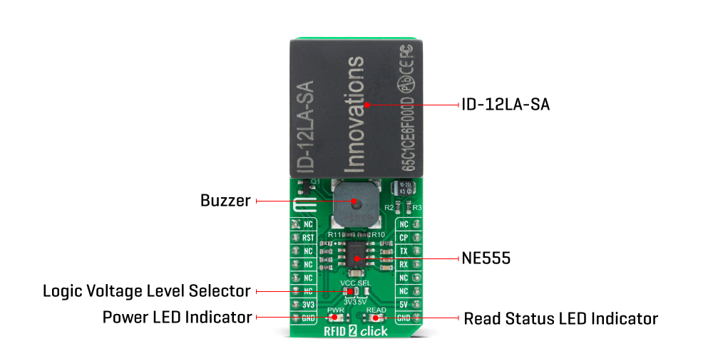
RFID 2 Click is a compact add-on board that contains a stand-alone RFID reader with a built-in antenna easy-to-use for embedded applications. This board features the ID-12LA-SA, an advanced low-cost RFID reader module usable with 38 different tags from ID Innovations. This small 125kHz reader has a 9600bps TTL/RS232 output with Magnetic, Wiegand, or ASCII format, read ranges of 12cm and 18cm, and possesses a remotely controlled channel that can be used to operate with user peripherals. This Click board™ is designed to be used in stand-alone or remote-controlled applications to identify and track tags attached to objects.
RFID 2 Click is supported by a mikroSDK compliant library, which includes functions that simplify software development. This Click board™ comes as a fully tested product, ready to be used on a system equipped with the mikroBUS™ socket.
This product is no longer in stock
Availability date:
OFF
| Company | Stock | Price |
|---|---|---|
RFID 2 Click is based on the ID-12LA-SA, an advanced low-cost RFID reader module designed to be used in stand-alone or remote-controlled applications to identify and track tags attached to objects from ID Innovations. The ID-12LA-SA requires the supply voltage up to 5V, supports normal mode (autonomous mode) of operation, incorporates internal antennas, and has read ranges of 12cm and 18cm.
In normal mode, when a card is presented to the reader, the reader search up for the card in its EEROM memory (the EEROM area stores the password and the reader polling address as well as timing and other values), and if there is a match module sends feedback information through interrupt pin labeled as CP. This mode automatically ceases to operate if the reader module detects a valid polled command. It is crucial to mention the safety fact that provides protection in such a way that the reader requires a password authorization for system changes and addition or removal of cards. In this way, the EEROM can be made safe and can only be restored with the password.
The ID-12LA-SA module communicates with MCU using the UART interface that operates at 9600 bps by default configuration with commonly used UART RX and TX pins for data transfer. The ID-12LA-SA module sends the ID data to the TX UART pin for monitoring, and in Normal mode, the reader sends the ID data of every card that it reads. Additional functionality, as mentioned previously in the product description, such as Reset and ‘Card Present’ interrupt is provided and routed at RST and INT pins of the mikroBUS™ socket labeled as RST and CP.
The RFID 2 Click also features the CMT-8540S-SMT magnetic buzzer that sounds for approximately one second when a card is detected, controlled by the NE555 precision timer capable of producing highly accurate time delays from Texas Instruments. Signal frequency determines the sound pitch, and the duty cycle determines the amplitude (sound volume), so the user is left with the option of creating a sound pattern of their choice. It also possesses the card read status LED indicator labeled as READ that indicates a successful detection of ID card.
This Click board™ is designed to be operated with both 3.3V and 5V logic voltage levels that can be selected via VCC SEL jumper. This allows for both 3.3V and 5V capable MCUs to use the UART communication lines properly. However, the Click board™ comes equipped with a library that contains easy to use functions and an example code that can be used as a reference for further development.
Type
RFID/NFC
Applications
Can be used in stand-alone or remote-controlled applications to identify and track tags attached to objects.
On-board modules
RFID 2 Click is based on the ID-12LA-SA, an advanced low-cost RFID reader module designed to be used in stand-alone or remote-controlled applications to identify and track tags attached to objects from ID Innovations.
Key Features
Low power consumption, autonomous mode, remote controlled auxiliary Channel, long range 12cm and 18cm, and more.
Interface
UART
Feature
No ClickID
Compatibility
mikroBUS™
Click board size
L (57.15 x 25.4 mm)
Input Voltage
3.3V or 5V
This table shows how the pinout on RFID 2 Click corresponds to the pinout on the mikroBUS™ socket (the latter shown in the two middle columns).
| Notes | Pin | Pin | Notes | ||||
|---|---|---|---|---|---|---|---|
| NC | 1 | AN | PWM | 16 | NC | ||
| Reset | RST | 2 | RST | INT | 15 | CP | Card Present Interrupt |
| NC | 3 | CS | RX | 14 | TX | UART TX | |
| NC | 4 | SCK | TX | 13 | RX | UART RX | |
| NC | 5 | MISO | SCL | 12 | NC | ||
| NC | 6 | MOSI | SDA | 11 | NC | ||
| Power Supply | 3.3V | 7 | 3.3V | 5V | 10 | 5V | Power Supply |
| Ground | GND | 8 | GND | GND | 9 | GND | Ground |
| Label | Name | Default | Description |
|---|---|---|---|
| LD1 | PWR | - | Power LED Indicator |
| LD2 | READ | - | Read Status LED Indicator |
| JP1 | VCC SEL | Left | Power Supply Voltage Selection 3V3/5V: Left position 3V3, Right position 5V |
| PZ1 | BUZZER | - | Magnetic Buzzer Transducer |
| Description | Min | Typ | Max | Unit |
|---|---|---|---|---|
| Supply Voltage | +3 | - | +5.4 | V |
| Maximum Output Current | -5 | - | +5 | mA |
| Read Range | 12 | - | 18 | cm |
| Frequency | - | 125 | - | kHz |
| Operating Temperature Range | -10 | - | +50 | °C |
We provide a library for the RFID 2 Click on our LibStock page, as well as a demo application (example), developed using MikroElektronika compilers. The demo can run on all the main MikroElektronika development boards.
Library Description
Initializes and defines UART bus driver, and defines driver's functions for comunication reading and writing. The library includes function for read ID (card / tag) in hex or dec value. The user also has the function for reset device and function for get interrupt pin state.
Key functions:
uint8_t rfid2_get_id_card( uint8_t *id_card ) - Function for get ID cardvoid rfid2_reset() - Function for reset deviceuint32_t rfid2_hex_to_dec (char *id_hex) - Function for convert ID card [HEX] to ID card [DEC]Examples description
The application is composed of three sections :
void application_task ( )
{
    char id_card_hex[ 15 ] = { 0 };
    uint32_t id_card_dec;
    uint8_t card_error;
    char demo_text[ 20 ];

    memset( &id_card_hex, 0 , 15 );
    card_error = rfid2_get_id_card( &id_card_hex[ 0 ] );

    if ( card_error == RFID2_CARD_IS_SUCCESSFULLY_READ )
    {
        id_card_dec = rfid2_hex_to_dec( &id_card_hex[ 0 ] );
        mikrobus_logWrite( "* ID card(hex) is =  0x", _LOG_TEXT );
        mikrobus_logWrite( id_card_hex, _LOG_TEXT );
        mikrobus_logWrite( "* ID card(dec) is = ", _LOG_TEXT );
        LongWordToStr(id_card_dec, demo_text);
        mikrobus_logWrite( demo_text, _LOG_LINE );
        mikrobus_logWrite( "* Card is successfully read.", _LOG_LINE );
        mikrobus_logWrite( " ", _LOG_LINE );

        mikrobus_logWrite( ">>> Please, put your ID card. ", _LOG_LINE );
        Delay_ms( 100 );
    }
}
The full application code, and ready to use projects can be found on our LibStock page.
Other mikroE Libraries used in the example:
Additional notes and informations
Depending on the development board you are using, you may need USB UART click, USB UART 2 click or RS232 click to connect to your PC, for development systems with no UART to USB interface available on the board. The terminal available in all MikroElektronika compilers, or any other terminal application of your choice, can be used to read the message.
This Click board™ is supported with mikroSDK - MikroElektronika Software Development Kit. To ensure proper operation of mikroSDK compliant Click board™ demo applications, mikroSDK should be downloaded from the LibStock and installed for the compiler you are using.
For more information about mikroSDK, visit the official page.
NOTE: Please be advised that any peripheral devices or accessories shown connected to the Click board™ are not included in the package. Check their availability in our shop or in the YMAN section below.

$2.40

$889.00

$95.00

$549.00

$299.00

$29.00

$29.00

$6.59

$3.60

$119.00

$449.00

$349.00

$349.00

$349.00

$299.00

$269.00

$249.00

$209.00
