


OFF
GO LOCAL
| Company | Stock | Price |
|---|---|---|


MIKROE-5510
24 g
Status:
PWR Meter 3 Click - 90A is a compact add-on board that measures voltage and current through the connected load. This board features the ACS37800KMACLU-090B3-I2C, an I2C-configurable power monitoring solution from Allegro Microsystems, which simplifies the addition of power monitoring to many AC/DC powered systems. The ACS37800KMACLU-090B3-I2C’s Hall-effect-based current sensing technology achieves reinforced isolation ratings (4800 VRMS) alongside a reliable ±90A bidirectional current sensing. It also has two LED indicators for the realization of visual detection of some anomalies in operation, such as under/overvoltage and fast overcurrent fault detection. This Click board™ is suitable for many monitoring applications, such as power metering in information and communication equipment, embedded electronic applications, and similar.
PWR Meter 3 Click is fully compatible with the mikroBUS™ socket and can be used on any host system supporting the mikroBUS™ standard. It comes with the mikroSDK open-source libraries, offering unparalleled flexibility for evaluation and customization. What sets this Click board™ apart is the groundbreaking ClickID feature, enabling your host system to seamlessly and automatically detect and identify this add-on board.
NOTE: If you require a lower current measurement range, we also offer the PWR Meter 3 Click, based on the ACS37800KMACLU-030B3-I2C, for measuring currents up to 30A. For more details about the PWR Meter 3 Click - 30A, please visit its product page.
This product is no longer in stock
Availability date:
OFF
| Company | Stock | Price |
|---|---|---|
 DO NOT TOUCH THE BOARD WHILE THE LOAD IS CONNECTED!
Note: This Click board™ needs to be used by trained personnel only while applying high voltages. Special care should be taken when working with hazardous voltage levels.
PWR Meter 3 Click is based on the ACS37800KMACLU-090B3-I2C, a simple solution for voltage, current, and power monitoring from Allegro Microsystems, which simplifies the addition of power monitoring in 60Hz to many AC/DC applications. The ACS37800KMACLU-090B3-I2C includes a copper conduction path that generates a magnetic field proportional to the applied current, sensed differentially to reject errors introduced by common mode fields. It is particularly well suited for high isolation, achieving reinforced isolation ratings of 4800 VRMS and a reliable ±90A bidirectional current sensing range. With high configurability and integrated features, this Click board™ can fit most power monitoring applications.
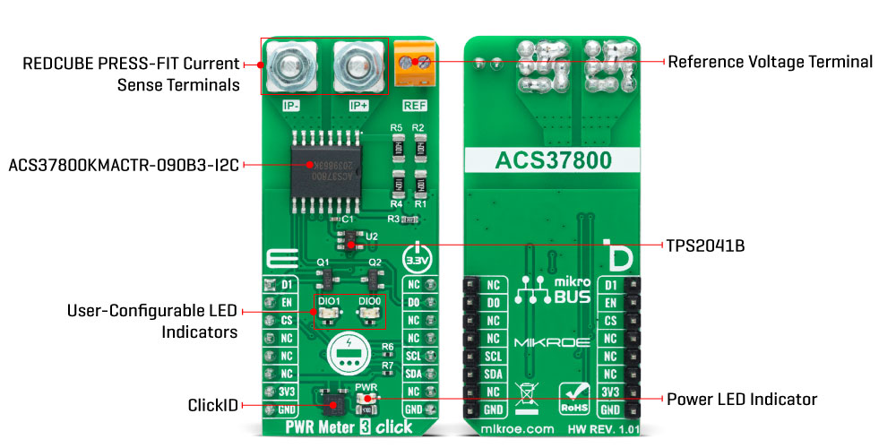
The ACS37800KMACLU-090B3-I2C measures the voltage applied to the REF terminal, in the range from 24 to 353Vrms, by resistor dividing it down to fit the input range of the onboard voltage sense amplifier and add isolation. On the other hand, the current applied to the current sensing terminals is measured using the integrated current loop and galvanically isolated Hall sensor. Both analog signals are then sampled using integrated high-accuracy ADCs before entering the digital system. The metrology engine later determines the frequency, calculates RMS values of current, voltage, and power, and provides a range of averaging and configuration options.
PWR Meter 3 Click communicates with an MCU using the standard I2C 2-Wire interface to read data and configure settings, supporting Standard Mode operation with a clock frequency of 100kHz and Fast Mode up to 400kHz. The ACS37800KMACLU-090B3-I2C can be enabled or disabled through the EN pin routed to the RST pin of the mikroBUS™ socket, hence, offering a switch operation to turn ON/OFF power delivery to the ACS37800KMACLU-090B3-I2C via TPS2041B.
Along with the ability to measure current and voltage, it also has two LED indicators, DIO0 and DIO1, for the realization of visual detection of some anomalies in operation, such as undervoltage and overvoltage reporting, and fast overcurrent fault detection. The DIO0 LED default state application is for zero crossing, while DIO1 stands for overcurrent detection. In addition to the LEDs, this information can also be detected through the INT and AN pins of the mikroBUS™ socket, marked as D0 and D1.
This Click board™ can be operated only with a 3.3V logic voltage level. The board must perform appropriate logic voltage level conversion before using MCUs with different logic levels. However, the Click board™ comes equipped with a library containing functions and an example code that can be used as a reference for further development.
Type
Measurements
Applications
Can be used for power metering in information and communication equipment, embedded electronic applications, and more
On-board modules
ACS37800KMACLU-090B3-I2C - power monitoring solution from Allegro Microsystems
Key Features
High accuracy power monitoring for AC and DC applications, certified for high reinforced isolation, Hall-effect based, anomaly detection, I2C interface, user-programmable thresholds, and more
Interface
I2C
Feature
ClickID
Compatibility
mikroBUS™
Click board size
L (57.15 x 25.4 mm)
Input Voltage
3.3V
This table shows how the pinout on PWR Meter 3 Click - 90A corresponds to the pinout on the mikroBUS™ socket (the latter shown in the two middle columns).
| Notes | Pin | Pin | Notes | ||||
|---|---|---|---|---|---|---|---|
| Overcurrent Fault | D1 | 1 | AN | PWM | 16 | NC | |
| Device Enable | EN | 2 | RST | INT | 15 | D0 | Zero Crossing |
| ID COMM | CS | 3 | CS | RX | 14 | NC | |
| NC | 4 | SCK | TX | 13 | NC | ||
| NC | 5 | MISO | SCL | 12 | SCL | I2C Clock | |
| NC | 6 | MOSI | SDA | 11 | SDA | I2C Data | |
| Power Supply | 3.3V | 7 | 3.3V | 5V | 10 | NC | |
| Ground | GND | 8 | GND | GND | 9 | GND | Ground |
| Label | Name | Default | Description |
|---|---|---|---|
| LD1 | PWR | - | Power LED Indicator |
| LD2 | DIO1 | - | User-Configurable LED Indicator |
| LD3 | DIO0 | - | User-Configurable LED Indicator |
| Description | Min | Typ | Max | Unit |
|---|---|---|---|---|
| Supply Voltage | - | 3.3 | - | V |
| Operating Current Range | -90 | - | +90 | A |
| Operating Voltage Range | 24 | - | 353 | VRMS |
| Sensitivity | - | 305.6 | - | LSB/A |
We provide a library for the PWR Meter 3 Click - 90A as well as a demo application (example), developed using MIKROE compilers. The demo can run on all the main MIKROE development boards.
Package can be downloaded/installed directly from NECTO Studio Package Manager (recommended), downloaded from our LibStock™ or found on MIKROE github account.
Library Description
This library contains API for PWR Meter 3 Click - 90A driver.
Key functions
pwrmeter3_get_dio0_pin This function returns the DIO0 pin logic state.
pwrmeter3_get_dio1_pin This function returns the DIO1 pin logic state.
pwrmeter3_read_average_rms This function reads the voltage and current RMS measurements averaged from a specified number of samples.
Example Description
This example demonstrates the use of PWR Meter 3 Click - 90A by reading and displaying the voltage, current, and power RMS measurements.
void application_task ( void )
 {
     float v_rms, i_rms;
     if ( PWRMETER3_OK == pwrmeter3_read_average_rms ( &pwrmeter3, &v_rms, &i_rms, PWRMETER3_DEF_AVG_SAMPLES ) )
     {
         if ( !pwrmeter3_get_dio0_pin ( &pwrmeter3 ) )
         {
             log_printf ( &logger, " Over-voltage detected!rn" );
         }
         if ( !pwrmeter3_get_dio1_pin ( &pwrmeter3 ) )
         {
             log_printf ( &logger, " Under-voltage detected!rn" );
         }
         log_printf ( &logger, " Voltage: %.2f Vrn", v_rms );
         log_printf ( &logger, " Current: %.2f Arn", i_rms );
         log_printf ( &logger, " Power: %.2f Wrnn", i_rms * v_rms );
     }
 }
The full application code, and ready to use projects can be installed directly from NECTO Studio Package Manager (recommended), downloaded from our LibStock™ or found on MIKROE github account.
Other MIKROE Libraries used in the example:
Additional notes and informations
Depending on the development board you are using, you may need USB UART click, USB UART 2 Click or RS232 Click to connect to your PC, for development systems with no UART to USB interface available on the board. UART terminal is available in all MIKROE compilers.
This Click board™ is supported with mikroSDK - MIKROE Software Development Kit. To ensure proper operation of mikroSDK compliant Click board™ demo applications, mikroSDK should be downloaded from the LibStock and installed for the compiler you are using.
For more information about mikroSDK, visit the official page.
NOTE: Please be advised that any peripheral devices or accessories shown connected to the Click board™ are not included in the package. Check their availability in our shop or in the YMAN section below.

$889.00

$95.00

$549.00

$299.00

$29.00

$29.00

$3.30

$3.60

$119.00

$349.00

$299.00

$449.00

$349.00

$349.00

$269.00

$249.00

$209.00
