


OFF
GO LOCAL
| Company | Stock | Price |
|---|---|---|


MIKROE-3991
17 g
Status:
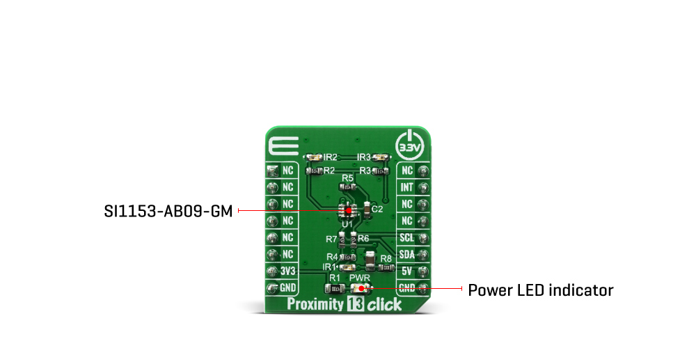
Proximity 13 Click based on SI1153-AB09-GMR IC from Silicon Labs that can be used as an proximity, and gesture detector with I2C digital interface and programmable-event interrupt output. The host can send command the Proximity 13 click to initiate on-demand proximity measurements. The host can also place the click board in an autonomous operational state where it performs measurements at set intervals and interrupts the host either after each measurement is completed or whenever the sample is larger/smaller than a set threshold value or exits/enters a set threshold window.
Proximity 13 Click board™ is supported by a mikroSDK compliant library, which includes functions that simplify software development. This Click board™ comes as a fully tested product, ready to be used on a system equipped with the mikroBUS™ socket.
This product is no longer in stock
Availability date:
OFF
| Company | Stock | Price |
|---|---|---|
Proximity 13 click features touchless sensor IC that includes dual 23-bit analog-to-digital converters, an integrated high-sensitivity array of visible and infrared photodiodes, a digital signal processor, and three integrated LED drivers with programmable drive levels. The photodiode response and associated digital conversion circuitry provide excellent immunity to artificial light flicker noise and natural light flutter noise.
By default, the measurement parameters are optimized for indoor ambient light levels, where it is possible to detect low light levels. For operation under direct sunlight, the ADC can be programmed to operate in a high signal operation so that it is possible to measure direct sunlight without overflowing.
The Proximity 13 click is capable of measuring visible and infrared light. However, the visible photodiode is also influenced by infrared light. The measurement of illuminance requires the same spectral response as the human eye. If an accurate lux measurement is desired, the extra IR response of the visible-light photodiode must be compensated. Therefore, to allow the host to make corrections to the infrared light’s influence, SI1153-AB09-GMR reports the infrared light measurement on a separate channel. The separate visible and IR photodiodes lend themselves to a variety of algorithmic solutions. The host can then take these two measurements and run an algorithm to derive an equivalent lux level as perceived by a human eye. Having the IR correction algorithm running in the host allows for the most flexibility in adjusting for system-dependent variables. For example, if the glass used in the system blocks visible light more than infrared light, the IR correction needs to be adjusted.
Over distances of less than 50 cm, the dual-port active reflection proximity detector has significant advantages over single-port, motion-based infrared systems, which are only good for triggered events. Motion-based infrared detectors identify objects within proximity, but only if they are moving. Single-port motion-based infrared systems are ambiguous about stationary objects even if they are within the proximity field. The Proximity 13 click can reliably detect an object entering or exiting a specified proximity field, even if the object is not moving or is moving very slowly. However, beyond about 30–50 cm, even with good optical isolation, single-port signal processing may be required due to static reflections from nearby objects, such as tables, walls, etc. If motion detection is acceptable, the SI1153-AB09-GMR can achieve ranges of up to 50 cm, through a single product window.
Since the three infrared LEDs are placed in an L-shaped configuration, it is possible to triangulate an object within the three-dimensional proximity field. Thus, a touchless user interface can be implemented with the aid of host software.
Type
Proximity
Applications
Wearables, Handsets, Display backlight control, Consumer electronics
On-board modules
SI1153-AB09-GMR
Key Features
Proximity detector, three independet LED drivers, operates in direct sunlight with on die 940 nm pasband filter, internal and external wake support
Interface
GPIO,I2C
Feature
No ClickID
Compatibility
mikroBUS™
Click board size
S (28.6 x 25.4 mm)
Input Voltage
3.3V
This table shows how the pinout on Proximity 13 click corresponds to the pinout on the mikroBUS™ socket (the latter shown in the two middle columns).
| Notes | Pin | Pin | Notes | ||||
|---|---|---|---|---|---|---|---|
| NC | 1 | AN | PWM | 16 | NC | ||
| NC | 2 | RST | INT | 15 | INT | Interrupt | |
| NC | 3 | CS | RX | 14 | NC | ||
| NC | 4 | SCK | TX | 13 | NC | ||
| NC | 5 | MISO | SCL | 12 | SCL | I2C Clock | |
| NC | 6 | MOSI | SDA | 11 | SDA | I2C Data | |
| Power Supply | 3.3V | 7 | 3.3V | 5V | 10 | +5V | Power supply |
| Ground | GND | 8 | GND | GND | 9 | GND | Ground |
| Label | Name | Default | Description |
|---|---|---|---|
| PWR | LED GREEN | - | Power LED Indicator |
| IR1, IR2, IR3 | IR LED | - | Infrared LED |
We provide a library for the Proximity 13 Click on our LibStock page, as well as a demo application (example), developed using MikroElektronika compilers. The demo can run on all the main MikroElektronika development boards.
Library Description
Librari provides functions for reading and writing to registers. You have functions for setting parameters, sending commands and configurating device channels. There is function for reading all channels if they are enabled.
Key functions:
uint8_t proximity13_generic_read ( uint8_t reg_adr ) - Generic read function from registersvoid proximity13_generic_write ( uint8_t reg_adr, uint8_t write_data ) - Generic write function to registersuint8_t proximity13_get_int_pin_status ( void ) - Function for reading status of int pinuint8_t proximity13_send_command ( uint8_t cmd_val ) - Function for sending commandsuint8_t proximity13_set_parameter ( uint8_t param, uint8_t cmd_val ) - Function for setting parametersuint8_t porximity13_config_channel ( uint8_t chn_num, proximity13_cfg_t cfg_val ) - Function for configurating specific channelvoid proximity13_read_channels ( proximity13_chn_val_t *chn_val ) - Fucnction for reading from all enabled channelsExamples description
The application is composed of three sections :
void application_task ( )
{
    proximity13_chn_val_t chn_val;
    char txt[ 30 ];

    proximity13_read_channels( &chn_val );

    WordToStr( chn_val.channel_1, txt );
    mikrobus_logWrite( "Data :", _LOG_TEXT );
    mikrobus_logWrite( txt, _LOG_LINE );

    Delay_ms ( 100 );
}
The full application code, and ready to use projects can be found on our LibStock page.
Other mikroE Libraries used in the example:
Additional notes and informations
Depending on the development board you are using, you may need USB UART click, USB UART 2 click or RS232 click to connect to your PC, for development systems with no UART to USB interface available on the board. The terminal available in all MikroElektronika compilers, or any other terminal application of your choice, can be used to read the message.
This Click board™ is supported with mikroSDK - MikroElektronika Software Development Kit. To ensure proper operation of mikroSDK compliant Click board™ demo applications, mikroSDK should be downloaded from the LibStock and installed for the compiler you are using.
For more information about mikroSDK, visit the official page.
NOTE: Please be advised that any peripheral devices or accessories shown connected to the Click board™ are not included in the package. Check their availability in our shop or in the YMAN section below.

$889.00

$95.00

$549.00

$299.00

$29.00

$29.00

$6.59

$3.60

$119.00

$449.00

$349.00

$349.00

$349.00

$299.00

$269.00

$249.00

$209.00
