


OFF
GO LOCAL
| Company | Stock | Price |
|---|---|---|


MIKROE-6623
20 g
Status:
Power Step Click is a compact add-on board designed for control of high-power two-phase bipolar stepper motors in industrial applications. It is based on the A4989SLD gate driver with integrated microstepping translator from Allegro Microsystems. This Click board uses external N-channel MOSFETs to deliver motor currents up to 20A at supply voltages from 12V to 35V, and supports full-, half-, quarter-, and sixteenth-step resolutions via a simple STEP/DIR interface. Key features include programmable decay modes (slow, mixed, fast), a REF trimmer for fine-tuning motor current, and a selectable synchronous rectification mode. Power Step Click is ideal for industrial automation, CNC machinery, robotic platforms, and any application requiring accurate and efficient high-power stepper motor control.
Power Step Click is fully compatible with the mikroBUS™ socket and can be used on any host system supporting the mikroBUS™ standard. It comes with the mikroSDK open-source libraries, offering unparalleled flexibility for evaluation and customization. What sets this Click board™ apart is the groundbreaking ClickID feature, enabling your host system to automatically detect and identify this add-on board.
NOTE: For optimal thermal performance, MIKROE provides high-quality aluminum and copper heatsinks with adhesive tapes that are available for purchase in its shop. These heatsinks offer the flexibility to enhance the cooling of various components (in this case, the power MOSFETs), ensuring your system runs efficiently and reliably.
This product is no longer in stock
Availability date:
OFF
| Company | Stock | Price |
|---|---|---|
Power Step Click is based on the A4989SLD, a dual full-bridge MOSFET driver with a microstepping translator from Allegro Microsystems. Designed to control higher power industrial two-phase stepper motors typically ranging from 30 to 500 watts, this board uses eight external N-channel power MOSFETs (IPZ40N04S5L-4R8) to deliver motor currents up to 20A at operating voltages between 12 and 35V on the VIN terminal. At the core of the Power Step Click, the A4989SLD features two sinusoidal DACs that serve as reference voltage generators for two individual fixed off-time PWM current controllers, ensuring precise current regulation across both full-bridge driver outputs. In addition to the internal DACs, the board includes a REF trimmer that allows users to manually set the reference voltage for current regulation, providing an extra layer of flexibility when fine-tuning the motor current according to specific application requirements. The Power Step Click is an ideal solution for engineers seeking a robust and flexible stepper motor driver platform that minimizes control complexity while offering high power performance.
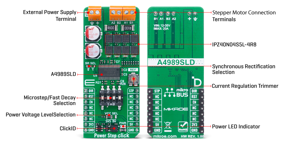
The board is equipped with a simple two-wire control interface - step and direction (STP and DIR) - enabling microstepping control at selectable resolutions of full, half, quarter, and sixteenth steps, configured via combination of multifunctional switch pins 3 and 4. The internal translator logic of the A4989SLD simplifies implementation by eliminating the need for high-frequency control signals or complex phase-sequencing, as each input pulse on the STP pin directly advances the motor by one step at the chosen resolution. Additionally, the driver supports multiple decay modes - slow, mixed, and fast - which can be created using multifunctional switch pins 1 and 2 to select the proportion of fast decay when mixed decay is active. This intelligent decay mode configuration contributes to quieter operation, improved step accuracy, and lower overall power dissipation.
In addition to the STP pin used for stepping control, Power Step Click incorporates several other control inputs to enhance the flexibility and performance. The DIR pin functions as the direction input, determining the rotational direction of the motor - when held LOW, the motor rotates clockwise, and when held HIGH, it rotates counter-clockwise. Importantly, any change in the DIR pin state takes effect only on the rising edge of the next pulse on the STP pin, ensuring accurate directional control synchronized with the stepping logic.
The board also includes an RST pin that serves to reset the A4989SLD IC, returning it to a known default state when triggered, as well as an EN pin that acts as an output enable signal. When the EN pin is asserted, the power output stages are activated, allowing motor control; when deasserted, all outputs are disabled, putting the system into a low-power or idle state. Additionally, Power Step Click features a jumper labeled SR SEL, which is used to set the behavior of the synchronous rectification feature.
When the SR SEL jumper is in position 0 (active mode), the device actively prevents current reversal by disabling synchronous rectification once a zero-current condition is detected, thus stopping the motor windings from conducting in the reverse direction. This mode is optimal for reducing power dissipation through the MOSFETs while maintaining precise current control. Alternatively, when SR SEL is set to position 1 (disabled mode), synchronous rectification is turned off entirely.
This Click board™ can operate with either 3.3V or 5V logic voltage levels selected via the VCC SEL jumper. This way, both 3.3V and 5V capable MCUs can use the communication lines properly. Also, this Click board™ comes equipped with a library containing easy-to-use functions and an example code that can be used as a reference for further development.
Type
Stepper
Applications
Ideal for industrial automation, CNC machinery, robotic platforms, and any application requiring accurate and efficient high-power stepper motor control
On-board modules
A4989SLD - dual full-bridge MOSFET driver with a microstepping translator from Allegro Microsystems
Key Features
High-power stepper motor control, eight external N-channel MOSFETs, support for full-, half-, quarter-, and sixteenth-step microstepping, integrated sinusoidal DACs for smooth current regulation, adjustable reference voltage via onboard REF trimmer, selectable decay modes including slow, mixed, and fast, direction and step input control interface, reset and output enable functionality, configurable synchronous rectification, and more
Interface
GPIO,PWM
Feature
ClickID
Compatibility
mikroBUS™
Click board size
L (57.15 x 25.4 mm)
Input Voltage
3.3V or 5V,External
This table shows how the pinout on Power Step Click corresponds to the pinout on the mikroBUS™ socket (the latter shown in the two middle columns).
| Notes | Pin | Pin | Notes | ||||
|---|---|---|---|---|---|---|---|
| Direction Control | DIR | 1 | AN | PWM | 16 | STP | Stepping Control |
| Reset / ID SEL | RST | 2 | RST | INT | 15 | NC | |
| Output Enable / ID COMM | EN | 3 | CS | RX | 14 | NC | |
| NC | 4 | SCK | TX | 13 | NC | ||
| NC | 5 | MISO | SCL | 12 | NC | ||
| NC | 6 | MOSI | SDA | 11 | NC | ||
| Power Supply | 3.3V | 7 | 3.3V | 5V | 10 | 5V | Power Supply |
| Ground | GND | 8 | GND | GND | 9 | GND | Ground |
| Label | Name | Default | Description |
|---|---|---|---|
| LD1 | PWR | - | Power LED Indicator |
| JP1 | VCC SEL | Left | Power Voltage Level Selection 3V3/5V: Left position 3V3, Right position 5V |
| JP2 | SR SEL | Left | Synchronous Rectification Selection 0/1: Left position 0, Right position 1 |
| RV1 | REF | - | Current Regulation Trimmer |
| Description | Min | Typ | Max | Unit |
|---|---|---|---|---|
| Supply Voltage | 3.3 | - | 5 | V |
| External Supply Voltage | 12 | - | 35 | V |
| Output Current (Peak) | - | - | 20 | A |
Power Step Click demo application is developed using the NECTO Studio, ensuring compatibility with mikroSDK's open-source libraries and tools. Designed for plug-and-play implementation and testing, the demo is fully compatible with all development, starter, and mikromedia boards featuring a mikroBUS™ socket.
Example Description
This example demonstrates the use of the Power Step Click board by driving the motor in both directions for a desired number of steps.
Key Functions
powerstep_cfg_setup This function initializes Click configuration structure to initial values.powerstep_init This function initializes all necessary pins and peripherals used for this Click board.powerstep_reset_device This function resets the device by setting the RST pin logic state.powerstep_drive_motor This function drives the motor for the specific number of steps at the selected speed.Application Init
Initializes the driver and resets the device.
Application Task
Drives the motor clockwise for 100 slow steps and 300 medium speed steps and then counter-clockwise for 400 fast steps with a 1 second delay on driving mode change. All data is being logged on the USB UART where you can track the program flow.
Application Output
This Click board can be interfaced and monitored in two ways:
Additional Notes and Information
The complete application code and a ready-to-use project are available through the NECTO Studio Package Manager for direct installation in the NECTO Studio. The application code can also be found on the MIKROE GitHub account.
NOTE: Please be advised that any peripheral devices or accessories shown connected to the Click board™ are not included in the package. Check their availability in our shop or in the YMAN section below.

$889.00

$95.00

$549.00

$299.00

$29.00

$29.00

$6.59

$3.60

$119.00

$449.00

$349.00

$349.00

$349.00

$299.00

$269.00

$249.00

$209.00
