


OFF
GO LOCAL
| Company | Stock | Price |
|---|---|---|


MIKROE-4905
20 g
Status:
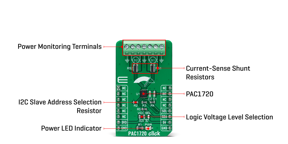
PAC1720 Click is a compact add-on board that contains an energy monitoring solution. This board features the PAC1720, an I2C configurable dual high-side bidirectional current sensing monitor with precision voltage measurement capabilities from Microchip Technology. The PAC1720 measures the voltage developed across external sense resistors to represent the high-side current of a battery or voltage regulator. They also measure the SENSE+ pin voltage and use these estimated values to present a proportional average power calculation. The current sensing feature includes fault protection, where during a fault condition, the ALERT pin can be asserted or masked. This Click board™ performs power calculations enabling energy monitoring in industrial and embedded applications, power management systems, and many more.
PAC1720 Click is supported by a mikroSDK compliant library, which includes functions that simplify software development. This Click board™ comes as a fully tested product, ready to be used on a system equipped with the mikroBUS™ socket.
This product is no longer in stock
Availability date:
OFF
| Company | Stock | Price |
|---|---|---|
PAC1720 Click as its foundation uses the PAC1720, a dual bidirectional high-side current-sensing device with precision voltage measurement capabilities from Microchip Technology. It measures the voltage developed across external sense resistors to represent the high-side current of a battery or voltage regulator, then digitizes it with a variable resolution Sigma-Delta ADC and transmits it over the I2C protocol. The PAC1720 also measures the SENSE+ pin voltages and calculates average power over the integration period.
The PAC1720 has three states of operation: Active, Standby, and One-Shot Mode. In Active mode, the PAC1720 initiates conversion cycles for the programmed conversion rate. The Standby mode represents the lowest power state, where there are no conversion cycles. The majority of circuitry is powered-down to reduce supply current to a minimum. While the device is in the Standby state, the host can initiate a conversion cycle on-demand using One-Shot mode. After the conversion cycle is complete, the device will return to the Standby state.
PAC1720 Click communicates with MCU using the standard I2C 2-Wire interface to read data and configure settings, supporting operation with a clock frequency up to 400kHz. Besides, it also allows the choice of its I2C slave address by positioning the SMD resistor of appropriate value labeled as R2, giving the user the ability to select one of eight possible slave addresses.
The current range allows for significant variations in measured current with high accuracy and the low voltage drop across the resistor. The PAC1720 has programmable high and low limits for current sense and bus voltage with a maskable alert signal labeled as INT, routed to the RST pin of the mikroBUS™ socket, to the host when an out-of-limit measurement occurs.
This Click board™ can operate with both 3.3V and 5V logic voltage levels selected via the VCC SEL jumper. This way, it is allowed for both 3.3V and 5V capable MCUs to use the I2C communication lines properly. However, the Click board™ comes equipped with a library containing easy-to-use functions and an example code that can be used, as a reference, for further development.
Type
Measurements
Applications
Can perform power calculations enabling energy monitoring in industrial and embedded applications, power management systems, and many more
On-board modules
PAC1720 - dual bidirectional high-side current-sensing device with precision voltage measurement capabilities from Microchip Technology
Key Features
Dual high-side bidirectional current sensor, power calculation, programmable sense voltage range, fault event indicator, I2C interface with selectable address, and more
Interface
I2C
Feature
No ClickID
Compatibility
mikroBUS™
Click board size
M (42.9 x 25.4 mm)
Input Voltage
3.3V or 5V
This table shows how the pinout on PAC1720 Click corresponds to the pinout on the mikroBUS™ socket (the latter shown in the two middle columns).
| Notes | Pin | Pin | Notes | ||||
|---|---|---|---|---|---|---|---|
| NC | 1 | AN | PWM | 16 | NC | ||
| NC | 2 | RST | INT | 15 | INT | Interrupt | |
| NC | 3 | CS | RX | 14 | NC | ||
| NC | 4 | SCK | TX | 13 | NC | ||
| NC | 5 | MISO | SCL | 12 | SCL | I2C Clock | |
| NC | 6 | MOSI | SDA | 11 | SDA | I2C Data | |
| Power Supply | 3.3V | 7 | 3.3V | 5V | 10 | 5V | Power Supply |
| Ground | GND | 8 | GND | GND | 9 | GND | Ground |
| Label | Name | Default | Description |
|---|---|---|---|
| LD1 | PWR | - | Power LED Indicator |
| JP1 | VCC SEL | Left | Logic Level Voltage Selection 3V3/5V: Left position 3V3, Right position 5V |
| R2 | R2 | Populated | I2C Slave Address Selection Jumper |
| Description | Min | Typ | Max | Unit |
|---|---|---|---|---|
| Supply Voltage | 3.3 | - | 5 | V |
| SENSE Pins Common-Mode Voltage Range | 0 | - | 40 | V |
| Accuracy | - | - | ±1 | % |
| Operating Temperature Range | -40 | +25 | +85 | °C |
We provide a library for the PAC1720 Click as well as a demo application (example), developed using MikroElektronika compilers. The demo can run on all the main MikroElektronika development boards.
Package can be downloaded/installed directly from NECTO Studio Package Manager(recommended way), downloaded from our LibStock™ or found on Mikroe github account.
Library Description
This library contains API for PAC1720 Click driver.
Key functions
pac1720_set_vsource_config This function sets the Voltage Source configuration (sample time and average samples) for the selected channel.
pac1720_set_vsense_config This function sets the Voltage Sense configuration (sample time, average samples, and sampling range) for the selected channel.
pac1720_get_measurements This function reads voltage, current, and power from the selected channel.
Example Description
This example demonstrates the use of PAC1720 Click board™ by reading the voltage, current, and power from both available channels.
void application_task ( void )
{
float voltage = 0, current = 0, power = 0;
if ( PAC1720_OK == pac1720_get_measurements ( &pac1720, PAC1720_CHANNEL_1, &voltage, ¤t, &power ) )
{
log_printf( &logger, " Channel 1:rn" );
log_printf( &logger, " U: %.3fV, I: %.3fA, P: %.3fWrn", voltage, current, power );
}
if ( PAC1720_OK == pac1720_get_measurements ( &pac1720, PAC1720_CHANNEL_2, &voltage, ¤t, &power ) )
{
log_printf( &logger, " Channel 2:rn" );
log_printf( &logger, " U: %.3fV, I: %.3fA, P: %.3fWrnn", voltage, current, power );
}
Delay_ms( 1000 );
}
The full application code, and ready to use projects can be installed directly from NECTO Studio Package Manager(recommended way), downloaded from our LibStock™ or found on Mikroe github account.
Other Mikroe Libraries used in the example:
Additional notes and informations
Depending on the development board you are using, you may need USB UART click, USB UART 2 Click or RS232 Click to connect to your PC, for development systems with no UART to USB interface available on the board. UART terminal is available in all MikroElektronika compilers.
This Click board™ is supported with mikroSDK - MikroElektronika Software Development Kit. To ensure proper operation of mikroSDK compliant Click board™ demo applications, mikroSDK should be downloaded from the LibStock and installed for the compiler you are using.
For more information about mikroSDK, visit the official page.
NOTE: Please be advised that any peripheral devices or accessories shown connected to the Click board™ are not included in the package. Check their availability in our shop or in the YMAN section below.

$889.00

$95.00

$549.00

$299.00

$29.00

$29.00

$6.59

$3.60

$119.00

$449.00

$349.00

$349.00

$349.00

$299.00

$269.00

$249.00

$209.00
