


OFF
ClickID
GO LOCAL
| Company | Stock | Price |
|---|---|---|


18 g
Status:
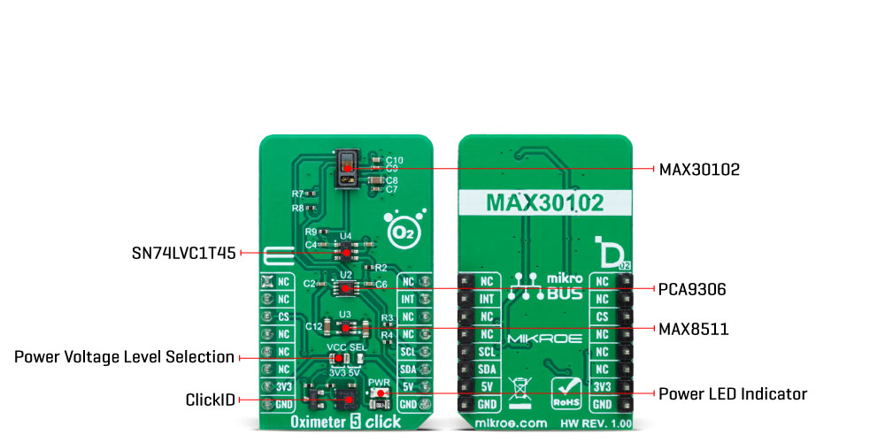
Oximeter 5 Click is a compact add-on board suitable for measuring blood oxygen saturation. This board features the MAX30102, integrated pulse oximetry, and heart-rate monitor module from Analog Devices. The MAX30102 includes internal LEDs, photodetectors, optical elements, and low-noise electronics with ambient light rejection. It operates on a single 1.8V power supply acquired from both mikroBUS™ power rails for the internal LEDs, communicating through a standard I2C compatible interface. The MAX30102 can be shut down through software with zero standby current, allowing the power rails to remain powered at all times. This Click board™ makes it an excellent choice for optical pulse oximetry and health monitoring applications.
Oximeter 5 Click is fully compatible with the mikroBUS™ socket and can be used on any host system supporting the mikroBUS™ standard. It comes with the mikroSDK open-source libraries, offering unparalleled flexibility for evaluation and customization. What sets this Click board™ apart is the groundbreaking ClickID feature, enabling your host system to seamlessly and automatically detect and identify this add-on board.
NOTE: This Click board™ is a development and prototyping tool only. It is not certified for clinical use and must not be used for diagnosing or treating medical conditions.
This product is no longer in stock
Availability date:
OFF
| Company | Stock | Price |
|---|---|---|
Oximeter 5 Click as its foundation uses the MAX30102, a high-sensitivity pulse oximeter and heart-rate sensor from Maxim Integrated, now part of Analog Devices. The MAX30102 integrates Red and IR LEDs, with 660nm red and 880nm IR wavelengths, to modulate LED pulses for oxygen saturation (SpO2) and heart rate measurements. The LED pulse width can be programmed to allow the algorithm to optimize SpO2 and HR accuracy and power consumption based on use cases.
The SpO2 subsystem of the MAX30102 contains ambient light cancellation (ALC), a continuous-time oversampling sigma-delta ADC with 18-bit resolution, and a proprietary discrete-time filter. The ALC has an internal Track/Hold circuit to cancel ambient light and increase the effective dynamic range. The MAX30102 also has an on-chip temperature sensor with an inherent resolution of 0.0625°C for calibrating the temperature dependence of the SpO2 subsystem.
The MAX30102 does not require a specific Power-Up sequence but requires a supply voltage of 1.8V to work correctly. Therefore, a small regulating LDO is used, the MAX8511, providing a 1.8V out of both 5V and 3.3V mikroBUS™ power rails. Also, it can be shut down through software with zero standby current, allowing the power rails to remain powered at all times.
Oximeter 5 Click communicates with MCU using the standard I2C 2-Wire interface with a maximum clock frequency of 400kHz. It is fully adjustable through software registers, and the digital output data is stored in a 32-deep FIFO within the device. Since the sensor for operation requires a power supply of 1.8V, this Click board™ also features the PCA9306 and SN74LVC1T45 voltage-level translators. The I2C interface bus lines are routed to the voltage-level translators allowing this Click board™ to work with both 3.3V and 5V MCUs properly. Also, it uses an interrupt pin, the INT pin of the mikroBUS™ socket, used for when an interrupt occurs, after the power is established, to alert the system that the MAX30102 is ready for operation.
This Click board™ can operate with both 3.3V and 5V logic voltage levels selected via the VCC SEL jumper. This way, it is allowed for both 3.3V and 5V capable MCUs to use the communication lines properly. However, the Click board™ comes equipped with a library containing easy-to-use functions and an example code that can be used, as a reference, for further development.
Type
Biometrics
Applications
Can be used for optical pulse oximetry and health monitoring applications
On-board modules
MAX30102 - high-sensitivity pulse oximeter and heart-rate sensor from Maxim Integrated, now part of Analog Devices
Key Features
Integrated optical components, fully integrated ADC, LED drivers, and timing core, low power consumption, fast data output capability, designed for ultralow direct optical reflections, and more
Interface
I2C
Feature
ClickID,No ClickID
Compatibility
mikroBUS™
Click board size
M (42.9 x 25.4 mm)
Input Voltage
3.3V or 5V
This table shows how the pinout on Oximeter 5 Click corresponds to the pinout on the mikroBUS™ socket (the latter shown in the two middle columns).
| Notes | Pin | Pin | Notes | ||||
|---|---|---|---|---|---|---|---|
| NC | 1 | AN | PWM | 16 | NC | ||
| NC | 2 | RST | INT | 15 | INT | Interrupt | |
| ID COMM | CS | 3 | CS | RX | 14 | NC | |
| NC | 4 | SCK | TX | 13 | NC | ||
| NC | 5 | MISO | SCL | 12 | SCL | I2C Clock | |
| NC | 6 | MOSI | SDA | 11 | SDA | I2C Data | |
| Power Supply | 3.3V | 7 | 3.3V | 5V | 10 | 5V | Power Supply |
| Ground | GND | 8 | GND | GND | 9 | GND | Ground |
| Label | Name | Default | Description |
|---|---|---|---|
| LD1 | PWR | - | Power LED Indicator |
| JP1 | VCC SEL | Left | Power Voltage Level Selection 3V3/5V: Left position 3V3, Right position 5V |
| Description | Min | Typ | Max | Unit |
|---|---|---|---|---|
| Supply Voltage | 3.3 | - | 5 | V |
| Red LED Wavelenght | 650 | 660 | 670 | nm |
| Infrared LED Wavelenght | 870 | 880 | 900 | nm |
| ADC Resolution | - | 18 | - | bits |
We provide a library for the Oximeter 5 Click as well as a demo application (example), developed using MIKROE compilers. The demo can run on all the main MIKROE development boards.
Package can be downloaded/installed directly from NECTO Studio Package Manager (recommended), downloaded from our LibStock™ or found on MIKROE github account.
Library Description
This library contains API for Oximeter 5 Click driver.
Key functions
oximeter5_read_sensor_data Oximeter 5 get sensor data function.
oximeter5_get_oxygen_saturation Oximeter 5 get oxygen saturation function.
oximeter5_read_temperature Oximeter 5 read temperature function.
Example Description
This library contains API for Oximeter 5 Click driver. The demo application reads and calculate SpO2 oxygen saturation data.
 void application_task ( void )
 {
     for ( uint8_t n_cnt = 25; n_cnt < 100; n_cnt++ )
     {
         aun_red_buffer[ n_cnt - 25 ] = aun_red_buffer[ n_cnt ];
         aun_ir_buffer[ n_cnt - 25 ] = aun_ir_buffer[ n_cnt ];

         if ( un_min > aun_red_buffer[ n_cnt ] )
         {
             un_min = aun_red_buffer[ n_cnt ];
         }

         if ( un_max < aun_red_buffer[ n_cnt ] )
         {
             un_max=aun_red_buffer[n_cnt];
         }
     }

     for ( uint8_t n_cnt = 75; n_cnt < 100; n_cnt++ )
     {
         un_prev_data = aun_red_buffer[ n_cnt - 1 ];
         while ( oximeter5_check_interrupt( &oximeter5 ) == OXIMETER5_INTERRUPT_ACTIVE );

         oximeter5_read_sensor_data( &oximeter5, &aun_red_buffer[ n_cnt ], &aun_ir_buffer[ n_cnt ] );

         if ( aun_red_buffer[ n_cnt ] > un_prev_data )
         {
             f_temp = aun_red_buffer[ n_cnt ]-un_prev_data;
             f_temp /= ( un_max - un_min );
             f_temp *= MAX_BRIGHTNESS;
             f_temp = un_brightness - f_temp;

             if ( f_temp < 0 )
             {
                 un_brightness = 0;
             }
             else
             {
                 un_brightness = ( uint32_t ) f_temp;
             }
         }
         else
         {
             f_temp = un_prev_data - aun_red_buffer[ n_cnt ];
             f_temp /= ( un_max - un_min );
             f_temp *= MAX_BRIGHTNESS;
             un_brightness += ( uint32_t ) f_temp;

             if ( un_brightness > MAX_BRIGHTNESS )
             {
                 un_brightness = MAX_BRIGHTNESS;
             }
         }

         if ( ( OXIMETER5_OK == oximeter5_get_oxygen_saturation( &aun_ir_buffer[ 0 ], 100, &aun_red_buffer[ 0 ], &n_spo2 ) ) )
         {
             if ( aun_ir_buffer[n_cnt] > 10000  )
             {
                 log_printf( &logger, "tIR    : %lu rn", aun_ir_buffer[ n_cnt ] );
                 log_printf( &logger, "tRED   : %lu rn", aun_red_buffer[ n_cnt ] );
                 log_printf( &logger, "- - - - - - - - - - - - - - -rn" );
                 log_printf( &logger, "tSPO2  : %d %%rn", ( uint16_t ) n_spo2 );
                 log_printf( &logger, "-----------------------------rn" );
                 Delay_ms( 100 );
             }
             else
             {
                 Delay_ms( 10 );
             }
         }
     }
 }
The full application code, and ready to use projects can be installed directly from NECTO Studio Package Manager (recommended), downloaded from our LibStock™ or found on MIKROE github account.
Other MIKROE Libraries used in the example:
Additional notes and informations
Depending on the development board you are using, you may need USB UART click, USB UART 2 Click or RS232 Click to connect to your PC, for development systems with no UART to USB interface available on the board. UART terminal is available in all MIKROE compilers.
This Click board™ is supported with mikroSDK - MIKROE Software Development Kit. To ensure proper operation of mikroSDK compliant Click board™ demo applications, mikroSDK should be downloaded from the LibStock and installed for the compiler you are using.
For more information about mikroSDK, visit the official page.
NOTE: Please be advised that any peripheral devices or accessories shown connected to the Click board™ are not included in the package. Check their availability in our shop or in the YMAN section below.

$889.00

$95.00

$549.00

$299.00

$29.00

$29.00

$3.30

$3.60

$119.00

$449.00

$349.00

$349.00

$349.00

$299.00

$269.00

$249.00

$209.00
