


OFF
GO LOCAL
| Company | Stock | Price |
|---|---|---|


MIKROE-1577
30 g
Status:
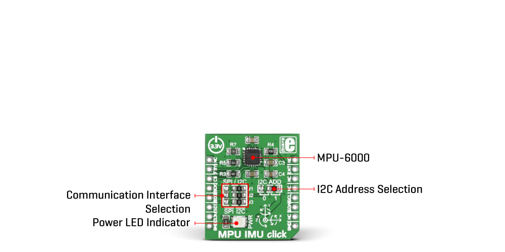
MPU IMU Click is a compact add-on board that can detect movement and acceleration. This board features the MPU-6000, an integrated 6-axis motion device from TDK InvenSense that combines a 3-axis gyroscope and accelerometer alongside a DMP (digital motion processor). The Digital Motion Processor engine is capable of processing complex 9-axis MotionFusion algorithms. Besides high sensitivity with a user-programmable full-scale range for the gyroscope and accelerometer, it also has a configurable host interface that supports I2C and SPI serial communication. This Click board™ makes the perfect solution for adding the ability to precisely and accurately track user motions, 3D remote controls, gesture recognition, and many others.
MPU IMU Click is supported by a mikroSDK compliant library, which includes functions that simplify software development. This Click board™ comes as a fully tested product, ready to be used on a system equipped with the mikroBUS™ socket.
This product is no longer in stock
Availability date:
OFF
| Company | Stock | Price |
|---|---|---|
MPU IMU Click is based on the MPU-6000, an integrated 6-axis motion device that combines a 3-axis gyroscope and accelerometer and a DMP (digital motion processor) from TDK InvenSense. The onboard gyroscope has a high sensitivity with a user-programmable full-scale range of ±250, ±500, ±1000, and ±2000dps, while the accelerometer has a full-scale programmable range of ±2g, ±4g, ±8g, and ±16g. This integrated circuit has high vibration tolerance, where its digital output of 6 or 9-axis MotionFusion data consists of a rotation matrix, quaternion, Euler angle, or row data format. The DMP engine offloads complex MotionFusion, sensor timing synchronization, and gesture detection.
The MPU-6000 has an integrated digital output temperature sensor and embedded algorithms for run-time bias and compass calibration, with no user intervention required. An on-chip 1024 Byte FIFO buffer allows the system to read data in burst and enter a low-power mode, lowering system power consumption.
MPU IMU Click allows using both I2C and SPI interfaces with a maximum frequency of 400kHz for I2C and 1MHz for SPI communication (20MHz for reading sensor and interrupt registers). The selection can be made by positioning SMD jumpers marked as SPI/I2C to an appropriate position. Note that all the jumpers' positions must be on the same side, or the Click board™ may become unresponsive. While the I2C interface is selected, the MPU-6000 allows choosing its I2C slave address using the I2C ADD SMD jumper to an appropriate position marked as 0 and 1.
This Click board™ also supports electronic video stabilization and GPS synchronization over a digital FSY pin. Programmable interrupt over an INT pin supports gesture recognition, panning, zooming, scrolling, free fall interrupt, high-G interrupt, zero-motion detection, and more. A pedometer functionality is also implemented, allowing the target board's MCU to sleep while DMP maintains the step count.
This Click board™ can be operated only with a 3.3V logic voltage level. The board must perform appropriate logic voltage level conversion before using MCUs with different logic levels. However, the Click board™ comes equipped with a library containing functions and an example code that can be used, as a reference, for further development.
Type
Acceleration,Gyroscope,Motion
Applications
Can be used for adding the ability to precisely and accurately track user motions, 3D remote controls, gesture recognition, and many others
On-board modules
MPU-6000 - integrated 6-axis motion device from TDK InvenSense
Key Features
9-Axis MotionFusion by the on-chip Digital Motion Processor, user-programmable full-scalle range, selectable interface, low power consumption, external sync signal, high resolution, sensitivity, programmable interrupt, and more
Interface
GPIO,I2C,SPI
Feature
No ClickID
Compatibility
mikroBUS™
Click board size
S (28.6 x 25.4 mm)
Input Voltage
3.3V
This table shows how the pinout on MPU IMU Click corresponds to the pinout on the mikroBUS™ socket (the latter shown in the two middle columns).
| Notes | Pin | Pin | Notes | ||||
|---|---|---|---|---|---|---|---|
| NC | 1 | AN | PWM | 16 | NC | ||
| Frame Sync | FSY | 2 | RST | INT | 15 | INT | Interrupt |
| SPI Chip Select | CS | 3 | CS | RX | 14 | NC | |
| SPI Clock | SCK | 4 | SCK | TX | 13 | NC | |
| SPI Data OUT | SDO | 5 | MISO | SCL | 12 | SCL | I2C Clock |
| SPI Data IN | SDI | 6 | MOSI | SDA | 11 | SDA | I2C Data |
| Power Supply | 3.3V | 7 | 3.3V | 5V | 10 | NC | |
| Ground | GND | 8 | GND | GND | 9 | GND | Ground |
| Label | Name | Default | Description |
|---|---|---|---|
| LD1 | PWR | - | Power LED Indicator |
| J1-J3 | SPI/I2C | Right | Communication Interface Selection SPI/I2C: Left position SPI, Right position I2C |
| J4 | I2C ADD | Right | I2C address Selection 0/1: Left position 0, Right position 1 |
| Description | Min | Typ | Max | Unit |
|---|---|---|---|---|
| Supply Voltage | - | 3.3 | - | V |
| Gyroscope Range | ±250 | - | ±2000 | dps |
| Accelerometer Range | ±2 | - | ±16 | g |
| Gyroscope Sensitivity | 16.4 | - | 131 | LSB/dps |
| Accelerometer Sensitivity | 2.048 | - | 16.384 | LSB/g |
We provide a library for the MPU IMU Click as well as a demo application (example), developed using Mikroe compilers. The demo can run on all the main Mikroe development boards.
Package can be downloaded/installed directly from NECTO Studio Package Manager(recommended), downloaded from our LibStock™ or found on Mikroe github account.
Library Description
This library contains API for MPU IMU Click driver.
Key functions
This function read Accel X-axis, Y-axis and Z-axis.
This function read Gyro X-axis, Y-axis and Z-axis.
This function reads temperature data.
Example Description
Example code performs acceleration, angular rate (gyroscopic), and temperature measurement.
 void application_task ( void )
 {
     mpuimu_read_accel( &mpuimu, &accel_data );
     Delay_ms ( 100 );
     mpuimu_read_gyro( &mpuimu, &gyro_data );
     Delay_ms ( 100 );
     temperature = mpuimu_read_temperature( &mpuimu );
     Delay_ms ( 100 );

     log_printf( &logger, "    Accel    |    Gyro    rn" );
     log_printf( &logger, "--------------------------rn" );
     log_printf( &logger, " X = %d  | X = %d rn", accel_data.accel_x, gyro_data.gyro_x );
     log_printf( &logger, " Y = %d  | Y = %d rn", accel_data.accel_y, gyro_data.gyro_y );
     log_printf( &logger, " Z = %d  | Z = %d rn", accel_data.accel_z, gyro_data.gyro_z );
     log_printf( &logger, "--------------------------rn" );
     log_printf( &logger, "      TEMP = %0.2f Crn", temperature );
     log_printf( &logger, "--------------------------rn" );

     software_reset ( &mpuimu );
     Delay_ms ( 1000 );
 }
The full application code, and ready to use projects can be installed directly from NECTO Studio Package Manager(recommended), downloaded from our LibStock™ or found on Mikroe github account.
Other Mikroe Libraries used in the example:
Additional notes and informations
Depending on the development board you are using, you may need USB UART click, USB UART 2 Click or RS232 Click to connect to your PC, for development systems with no UART to USB interface available on the board. UART terminal is available in all Mikroe compilers.
This Click board™ is supported with mikroSDK - Mikroe Software Development Kit. To ensure proper operation of mikroSDK compliant Click board™ demo applications, mikroSDK should be downloaded from the LibStock and installed for the compiler you are using.
For more information about mikroSDK, visit the official page.
NOTE: Please be advised that any peripheral devices or accessories shown connected to the Click board™ are not included in the package. Check their availability in our shop or in the YMAN section below.

$889.00

$95.00

$549.00

$299.00

$29.00

$29.00

$6.59

$3.60

$119.00

$349.00

$299.00

$449.00

$349.00

$349.00

$269.00

$249.00

$209.00
