


OFF
GO LOCAL
| Company | Stock | Price |
|---|---|---|


MIKROE-4510
17 g
Status:
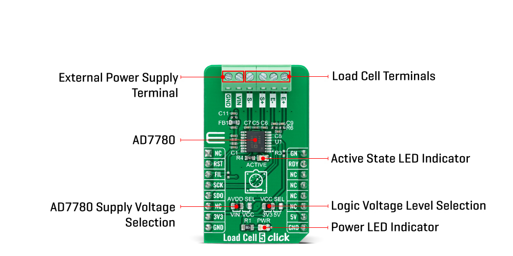
Load Cell 5 Click is a compact add-on board that represents a weigh scale solution. This board features the AD7780, a pin-programmable, low power, 24-bit sigma-delta ΣΔ ADC from Analog Devices. It interfaces directly to the load cell, where the low-level signal from the load cell is amplified by the AD7780’s internal low noise programmable gain amplifier programmed to operate with a gain of 128 or 1. It also has a power-down mode allowing the user to switch off the power to the bridge sensor and power-down the AD7780 when not converting, increasing the product battery life. This Click board™ has many features that make it a perfect solution for safety-critical and weight measurement applications.
Load Cell 5 Click is supported by a mikroSDK compliant library, which includes functions that simplify software development. This Click board™ comes as a fully tested product, ready to be used on a system equipped with the mikroBUS™ socket.
This product is no longer in stock
Availability date:
OFF
| Company | Stock | Price |
|---|---|---|
Load Cell 5 Click as its foundation uses the AD7780, a pin programmable, low power, low drift 24-bit ΣΔ ADC from Analog Devices, that includes a PGA and uses an internal clock. The AD7780 typically consumes only 330μA and simplifies this weigh scale design since most of the system building blocks are already on the chip. The AD7780 has two filter options selectable via FIL pin(low state - the 16.7Hz, high state - 10Hz) and a Power-Down Mode allowing the user to switch off the power to the bridge sensor and power-down the AD7780 when not converting, increasing the battery life.
Since the AD7780 provides an integrated solution for weighing scales, it interfaces directly to the load cell. The only required external components, which are also on the Click board™, are filters on the analog inputs and capacitors on the reference pins for EMC purposes. The low-level signal from the load cell is amplified by the AD7780’s internal PGA programmed via the PWM pin of the mikroBUS™ socket, labeled as GN, to operate with a gain of 128 or 1. The conversions from the AD7780 are then sent to the MCU through SPI serial interface, where the digital information is converted to weight.
This Click board™ uses the 6-wire load cell configuration, which has two sense pins, ground, power supply, and two output connections. The load cell differential SENSE lines connected to the AD7780 reference inputs create a ratiometric configuration immune to low-frequency changes in the power supply excitation voltage. Those sense pins are connected to the high and low sides of the Wheatstone bridge, where voltage can be accurately measured, regardless of the voltage drop due to the wiring resistance.
The AD7780 has separate analog and digital power supply pins. The analog and digital power supplies are independent of each other to be different, or the same, potentials achieved with the AVDD SEL jumper. This feature allows selecting the AD7780 power supply between an external power supply (2.7 - 5.25V) and logic voltage levels supplied via mikroBUS™ rails.
Load Cell 5 Click communicates with MCU using a standard SPI interface with a dual-purpose DOUT/RDY line. This line can function as a regular data output pin for the SPI interface or as a data ready pin (interrupt) labeled as RDY and routed on the INT pin of the mikroBUS socket. Also, it uses the RST pin on the mikroBUS™ socket, which performs the Hardware Reset function by putting this pin in a logic low state, and a blue diode labeled as ACTIVE used to indicate the device's Active Operational Status.
This Click board™ can operate with both 3.3V and 5V logic voltage levels selected via the VCC SEL jumper. This way, it is allowed for both 3.3V and 5V capable MCUs to properly use the I2C communication lines. However, the Click board™ comes equipped with a library containing easy-to-use functions and an example code that can be used, as a reference, for further development.
Type
Force
Applications
Can be used for safety-critical and weight measurement applications.
On-board modules
AD7780 - pin-programmable, low power, 24-bit sigma-delta ΣΔ ADC from Analog Devices
Key Features
Low power consumption, pin-programmable filter response, pin-programmable reset and gain, internal bridge power-down switch, independent interface power supply, and more.
Interface
SPI
Feature
No ClickID
Compatibility
mikroBUS™
Click board size
M (42.9 x 25.4 mm)
Input Voltage
3.3V or 5V,External
This table shows how the pinout on Load Cell 5 Click corresponds to the pinout on the mikroBUS™ socket (the latter shown in the two middle columns).
| Notes | Pin | Pin | Notes | ||||
|---|---|---|---|---|---|---|---|
| NC | 1 | AN | PWM | 16 | GN | Gain Selection | |
| Reset | RST | 2 | RST | INT | 15 | RDY | Interrupt / Data Ready |
| Filter Select | FIL | 3 | CS | RX | 14 | NC | |
| SPI Clock | SCK | 4 | SCK | TX | 13 | NC | |
| SPI Data OUT | SDO | 5 | MISO | SCL | 12 | NC | |
| NC | 6 | MOSI | SDA | 11 | NC | ||
| Power Supply | 3.3V | 7 | 3.3V | 5V | 10 | 5V | Power Supply |
| Ground | GND | 8 | GND | GND | 9 | GND | Ground |
| Label | Name | Default | Description |
|---|---|---|---|
| LD1 | PWR | - | Power LED Indicator |
| LD2 | ACTIVE | - | Active State LED Indicator |
| JP1 | VCC SEL | Left | Logic Level Voltage Selection 3V3/5V: Left position 3V3, Right position 5V |
| JP2 | AVDD SEL | Left | AD7780 Supply Voltage Selection VIN/VCC: Left position VIN, Right position VCC |
| Description | Min | Typ | Max | Unit |
|---|---|---|---|---|
| Supply Voltage | 3.3 | - | 5 | V |
| External Supply Voltage VIN | 2.7 | - | 5.25 | V |
| Resolution | 24 | - | - | bits |
| Operating Temperature Range | -40 | +25 | +105 | °C |
We provide a library for the Load Cell 5 Click as well as a demo application (example), developed using MikroElektronika compilers. The demo can run on all the main MikroElektronika development boards.
Package can be downloaded/installed directly from NECTO Studio Package Manager(recommended way), downloaded from our LibStock™ or found on mikroE github account.
Library Description
This library contains API for Load Cell 5 Click driver.
Key functions:
loadcell5_cfg_setup - Config Object Initialization function.loadcell5_init - Initialization function.loadcell5_default_cfg - Click Default Configuration function.Examples description
This library contains API for Load Cell 5 Click driver. The library initializes and defines the SPI bus drivers to read status and ADC data. The library also includes a function for tare, calibration and weight measurement.
The demo application is composed of two sections :
void application_task ( void ) {
    weight_val = loadcell5_get_weight( &loadcell5, &cell_data );

    log_printf(&logger, "   Weight : %.2f grn", weight_val );

    Delay_ms( 1000 );
}
The full application code, and ready to use projects can be installed directly from NECTO Studio Package Manager(recommended way), downloaded from our LibStock™ or found on mikroE github account.
Other mikroE Libraries used in the example:
Additional notes and informations
Depending on the development board you are using, you may need USB UART click, USB UART 2 click or RS232 click to connect to your PC, for development systems with no UART to USB interface available on the board. The terminal available in all MikroElektronika compilers, or any other terminal application of your choice, can be used to read the message.
This Click board™ is supported with mikroSDK - MikroElektronika Software Development Kit. To ensure proper operation of mikroSDK compliant Click board™ demo applications, mikroSDK should be downloaded from the LibStock and installed for the compiler you are using.
For more information about mikroSDK, visit the official page.
NOTE: Please be advised that any peripheral devices or accessories shown connected to the Click board™ are not included in the package. Check their availability in our shop or in the YMAN section below.

$889.00

$95.00

$549.00

$299.00

$29.00

$29.00

$3.30

$3.60

$119.00

$449.00

$349.00

$349.00

$349.00

$299.00

$269.00

$249.00

$209.00
