OFF
GO LOCAL
| Company | Stock | Price |
|---|---|---|

MIKROE-1999
24 g
Status:
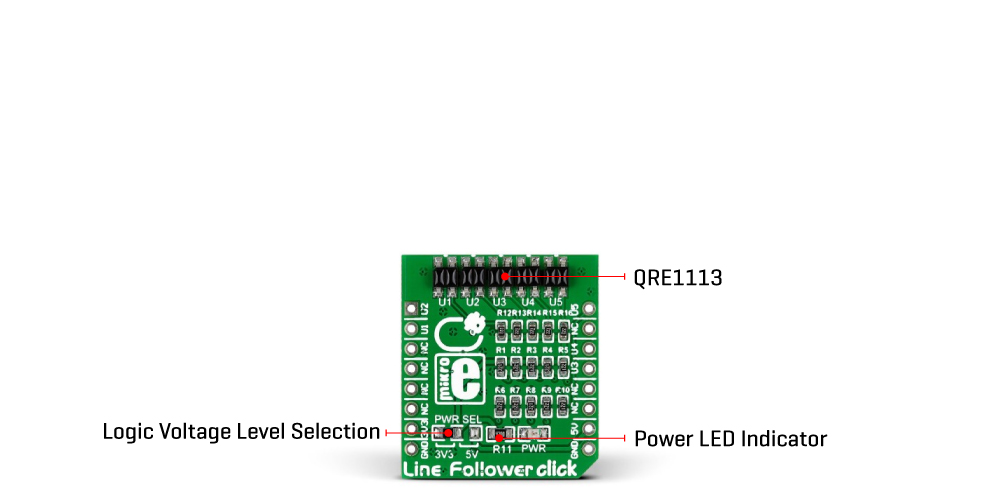
Line Follower Click is a compact add-on board that adds line following ability to your application based on infrared emission. This board features QRE1113, a miniature reflective object sensor from onsemi. With five QRE1113 sensors packed in an array, this Click board™ is capable of determining the exact position of the line. Each of the QRE1113 sensors consists of an infrared transmitter and an infrared emitter. This Click board™ makes the perfect solution for developing the line following robots or cars applications.
Line Follower Click is supported by a mikroSDK compliant library, which includes functions that simplify software development. This Click board™ comes as a fully tested product, ready to be used on a system equipped with the mikroBUS™ socket.
This product is no longer in stock
Availability date:
OFF
| Company | Stock | Price |
|---|---|---|

Line Follower Click is based on the QRE1113, a miniature reflective object sensor from onsemi. The array of the QRE1113 sensors is close to each other and points in the same direction, thus covering the more expansive space completely. The QRE1113 sensor is a no-surface contact sensing device and uses a phototransistor for output. By default, the sensor outputs a high logic level until they encounter a white surface which changes the output signal to a low logic state. Since there are five adjacent sensors, you can deduce the position or thickness of the white line from the combination of their outputs. The best results this Click board™ achieves are at a few millimeters from the surface to the sensors.

The Line Follower Click communicates with the host MCU by sending logical states to the corresponding pins of the mikroBUS™ socket. Each QRE1113 sensor has its own digital output; each routed through a single mikroBUS™ pin: U1, U2, U3, U4, and U5 (in place of default mikroBUS™ pins RST, AN, PWM, RX, and TX, respectively).
This Click board™ can operate with either 3.3V or 5V logic voltage levels selected via the PWR SEL jumper. This way, both 3.3V and 5V capable MCUs can use the communication lines properly. However, the Click board™ comes equipped with a library containing easy-to-use functions and an example code that can be used, as a reference, for further development.
Type
Optical
Applications
Can be used for developing the line following robots or cars applications
On-board modules
QRE1113 - miniature reflective object sensor from onsemi
Key Features
Five QRE1113 sensors allows wider following line space coverage, small distance from the covering surface, each phototransistor of the sensor has its own output line, low power consumption, and more
Interface
GPIO
Feature
No ClickID
Compatibility
mikroBUS™
Click board size
S (28.6 x 25.4 mm)
Input Voltage
3.3V or 5V
This table shows how the pinout on Line Follower Click corresponds to the pinout on the mikroBUS™ socket (the latter shown in the two middle columns).
| Label | Name | Default | Description |
|---|---|---|---|
| LD1 | PWR | - | Power LED Indicator |
| JP1 | PWR SEL | Left | Logic Level Voltage Selection 3V3/5V: Left position 3V3, Right position 5V |
| Description | Min | Typ | Max | Unit |
|---|---|---|---|---|
| Supply Voltage | 3.3 | - | 5 | V |
| Wavelength | - | 940 | - | nm |
We provide a library for the Line Follower Click as well as a demo application (example), developed using Mikroe compilers. The demo can run on all the main Mikroe development boards.
Package can be downloaded/installed directly from NECTO Studio Package Manager (recommended), downloaded from our LibStock™ or found on Mikroe github account.
Library Description
This library contains API for Line Follower Click driver.
Key functions
Example Description
Line Follower click carries an array of five QRE1113 miniature reflective object sensors, reading staus of AN, RST, PWM, TX and RX pins and reading tracking data.
 void application_task ( void )
 {
     linefollower_direction_t data_track;

     linefollower_data_track ( &linefollower, &data_track );

     log_printf( &logger, " %ut%ut%ut%ut%urn",
                 (uint16_t) data_track.u1,
                 (uint16_t) data_track.u2,
                 (uint16_t) data_track.u3,
                 (uint16_t) data_track.u4,
                 (uint16_t) data_track.u5);

     Delay_ms ( 100 );
 }
The full application code, and ready to use projects can be installed directly from NECTO Studio Package Manager (recommended), downloaded from our LibStock™ or found on Mikroe github account.
Other Mikroe Libraries used in the example:
Additional notes and informations
Depending on the development board you are using, you may need USB UART click, USB UART 2 Click or RS232 Click to connect to your PC, for development systems with no UART to USB interface available on the board. UART terminal is available in all Mikroe compilers.
This Click board™ is supported with mikroSDK - Mikroe Software Development Kit. To ensure proper operation of mikroSDK compliant Click board™ demo applications, mikroSDK should be downloaded from the LibStock and installed for the compiler you are using.
For more information about mikroSDK, visit the official page.
NOTE: Please be advised that any peripheral devices or accessories shown connected to the Click board™ are not included in the package. Check their availability in our shop or in the YMAN section below.