


OFF
GO LOCAL
| Company | Stock | Price |
|---|---|---|


MIKROE-1583
30 g
Status:
LDC1000 Click is a compact add-on board that measures the inductance change a conductive target causes when it moves into the inductor's AC magnetic field. This board features the LDC1000, a low-power inductance-to-digital converter (LDC) for inductive sensing solutions from Texas Instruments. This SPI-configurable sensor requires only the frequency between 5kHz and 5MHz to begin sensing, demonstrating the use of inductive sensing technology to sense and measure a conductive target object's presence, position, or composition. It comes with an example of a PCB sensor coil designed to provide the user with maximum flexibility. Also, onboard IN pins allow you to replace the offered detachable sensor and solder your own. This Click board™ is suitable for contactless, short-range sensing that enables high-resolution position sensing of conductive targets, even in harsh environments.
LDC1000 Click is supported by a mikroSDK compliant library, which includes functions that simplify software development. This Click board™ comes as a fully tested product, ready to be used on a system equipped with the mikroBUS™ socket.
This product is no longer in stock
Availability date:
OFF
| Company | Stock | Price |
|---|---|---|
LDC1000 Click is based on the LDC1000, a low-power inductance-to-digital converter from Texas Instruments. The LDC1000 simultaneously measures an LC resonator's impedance and resonant frequency by regulating the oscillation amplitude in a closed-loop configuration to a constant level while monitoring the energy dissipated by the resonator. By monitoring the amount of power injected into the resonator, the LDC1000 can determine the impedance value and return it as a digital value. In addition, the LDC1000 can also measure the oscillation frequency of the LC circuit, used to determine the inductance of the LC circuit, also given in a digital format. The LDC1000 has a sub-micron resolution in short-range applications suitable for precise short-range measurements of the position, motion, or composition of conductive targets.
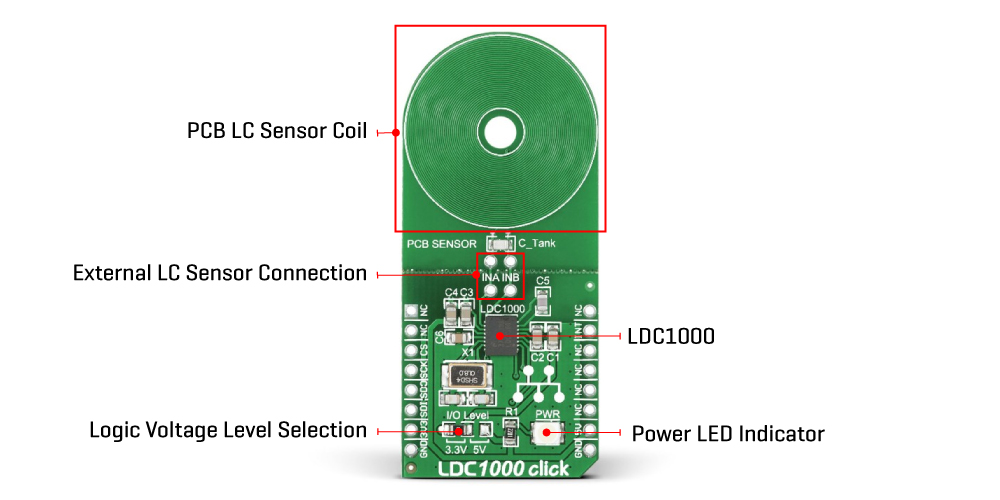
This Click board™ comes with a detachable sensor (an LC tank comprising a 36-turn PCB coil and a 100pF 1% NPO capacitor). The LDC measures the inductance change that a conductive target causes when it moves into the inductor's AC magnetic field to provide information about the target's position over a sensor coil. The inductance shift is caused by eddy currents (circulating currents) generated in the target due to the sensor's magnetic field. These currents make a secondary magnetic field that opposes the sensor field, causing a shift in the observed inductance, used for precise positioning of the target as it moves laterally over the sensor coil.
The LDC1000 communicates with MCU using the standard SPI serial interface with a maximum frequency of 4MHz. It also has an interrupt pin routed to the INT pin of the mikroBUS™ socket, which can be configured in three different ways by programming the interrupt mode register. An interrupt pin can act as a proximity switch with programmable hysteresis, a wake-up feature, or a data-ready pin indicating a valid condition for new data availability. Inductive sensing of this LDC is highly reliable where harsh conditions don't hinder the performance of LDC1000. Alongside the detachable sensor, the onboard INA and INB pins allow you to replace the provided sensor and solder your own.
This Click board™ can operate with both 3.3V and 5V logic voltage levels selected via the I/O Level jumper. This way, it is allowed for both 3.3V and 5V capable MCUs to use the communication lines properly. However, the Click board™ comes equipped with a library containing easy-to-use functions and an example code that can be used, as a reference, for further development.
Type
Inductance
Applications
Can be used for contactless, short-range sensing that enables high-resolution position sensing of conductive targets
On-board modules
LDC1000 - inductance-to-digital converter from Texas Instruments
Key Features
Low power consumption, short-range sensing technology, sub-micron precision, high durability, high flexibility, supports wide frequency range from 5kHz to 5MHz, remote sensor placement, high performance, reliability, and more
Interface
GPIO,SPI
Feature
No ClickID
Compatibility
mikroBUS™
Click board size
L (57.15 x 25.4 mm)
Input Voltage
3.3V or 5V
This table shows how the pinout on LDC1000 Click corresponds to the pinout on the mikroBUS™ socket (the latter shown in the two middle columns).
| Notes | Pin | Pin | Notes | ||||
|---|---|---|---|---|---|---|---|
| NC | 1 | AN | PWM | 16 | NC | ||
| NC | 2 | RST | INT | 15 | INT | Interrupt | |
| SPI Chip Select | CS | 3 | CS | RX | 14 | NC | |
| SPI Clock | SCK | 4 | SCK | TX | 13 | NC | |
| SPI Data OUT | SDO | 5 | MISO | SCL | 12 | NC | |
| SPI Data IN | SDI | 6 | MOSI | SDA | 11 | NC | |
| Power Supply | 3.3V | 7 | 3.3V | 5V | 10 | 5V | Power Supply |
| Ground | GND | 8 | GND | GND | 9 | GND | Ground |
| Label | Name | Default | Description |
|---|---|---|---|
| LD1 | PWR | - | Power LED Indicator |
| JP1 | I/O Level | Left | Logic Level Voltage Selection 3V3/5V: Left position 3V3, Right position 5V |
| - | INA-INB | - | External LC Sensor Connection |
| Description | Min | Typ | Max | Unit |
|---|---|---|---|---|
| Supply Voltage | 3.3 | - | 5 | V |
| LC Frequency Range | 5 | - | 5000 | kHz |
| L Resolution | - | 24 | - | bit |
We provide a library for the LDC 1000 Click as well as a demo application (example), developed using MikroElektronika compilers. The demo can run on all the main MikroElektronika development boards.
Package can be downloaded/installed directly from NECTO Studio Package Manager(recommended way), downloaded from our LibStock™ or found on Mikroe github account.
Library Description
This library contains API for LDC 1000 Click driver.
Key functions
This function reads the proximity data.
This function reads the inductance data.
This function reads the input voltage from the INT pin.
Example Description
This example showcases how to initialize and configure the logger and click modules and read and display proximity and impendance data.
 void application_task ( )
 {
     uint16_t proximity;
     uint16_t inductance;

     proximity = ldc1000_get_proximity_data( &ldc1000 );
     inductance = ldc1000_get_inductance_data( &ldc1000 );

     if ( ( ( proximity - old_proximity ) > LDC1000_SENSITIVITY ) &&
          ( ( old_proximity - proximity ) > LDC1000_SENSITIVITY ) )
     {
         log_printf( &logger, " * Proximity: %d rn", proximity );

         log_printf( &logger, " * Impendance: %f uHrn", inductance );

         old_proximity = proximity;

         log_printf( &logger, "--------------------rn" );
         Delay_100ms();
     }
 }
The full application code, and ready to use projects can be installed directly from NECTO Studio Package Manager(recommended way), downloaded from our LibStock™ or found on Mikroe github account.
Other Mikroe Libraries used in the example:
Additional notes and informations
Depending on the development board you are using, you may need USB UART click, USB UART 2 Click or RS232 Click to connect to your PC, for development systems with no UART to USB interface available on the board. UART terminal is available in all MikroElektronika compilers.
This Click board™ is supported with mikroSDK - MikroElektronika Software Development Kit. To ensure proper operation of mikroSDK compliant Click board™ demo applications, mikroSDK should be downloaded from the LibStock and installed for the compiler you are using.
For more information about mikroSDK, visit the official page.
NOTE: Please be advised that any peripheral devices or accessories shown connected to the Click board™ are not included in the package. Check their availability in our shop or in the YMAN section below.

$889.00

$95.00

$549.00

$299.00

$29.00

$29.00

$6.59

$3.60

$119.00

$449.00

$349.00

$349.00

$349.00

$299.00

$269.00

$249.00

$209.00
