


OFF
GO LOCAL
| Company | Stock | Price |
|---|---|---|


MIKROE-6611
21 g
Status:
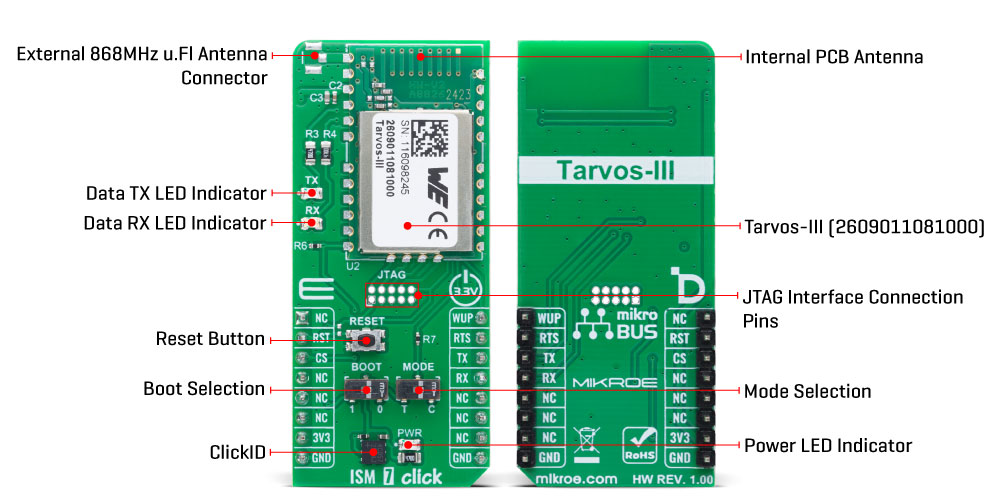
ISM 7 Click is a compact add-on board designed for long-range, low-power wireless communication in the 868MHz SRD band. It is based on the Tarvos-III (2609011081000) radio module from Würth Elektronik, which integrates the TI CC1310 sub-GHz transceiver with an onboard antenna. The board supports communication ranges up to 300 meters line-of-sight, features low-power operation, and includes both command and transparent UART modes for flexible data handling. It also offers Flooding Mesh networking, support for up to 65,535 devices, and an integrated software stack for quick deployment. ISM 7 Click is ideal for smart metering, industrial monitoring, building automation, agriculture, and other sub-GHz IoT applications.
ISM 7 Click is fully compatible with the mikroBUS™ socket and can be used on any host system supporting the mikroBUS™ standard. It comes with the mikroSDK open-source libraries, offering unparalleled flexibility for evaluation and customization. What sets this Click board™ apart is the groundbreaking ClickID feature, enabling your host system to seamlessly and automatically detect and identify this add-on board.
This product is no longer in stock
Availability date:
OFF
| Company | Stock | Price |
|---|---|---|
ISM 7 Click is based on the Tarvos-III (2609011081000) radio module from Würth Elektronik, designed for operation within the 868MHz SRD frequency band. This module integrates a high-performance sub-GHz transceiver, the Texas Instruments CC1310, which incorporates a 32-bit ARM Cortex-M3 processor, 128kB of Flash memory, and 20kB of RAM, enabling both communication handling and custom application code execution. The frequency range supported by the module spans from 863MHz to 870MHz, offering reliable connectivity over distances of up to 300 meters in line-of-sight conditions. With a transmission output power of -8dBm and an impressive receiver sensitivity of -104dBm, ISM 7 Click ensures stable wireless communication even in challenging environments. This Click board™ is ideal for a wide range of wireless communication applications such as smart metering, industrial monitoring, building automation, agricultural sensing systems, logistics tracking, and other long-range, low-power IoT applications that operate within the sub-GHz spectrum.
The module’s design emphasizes energy efficiency, making it suitable for battery-powered and low-power applications. It features an integrated software stack that supports advanced networking functionalities, including Flooding Mesh technology, which enables robust multi-hop communication across wide sensor networks. The addressing system is highly flexible, allowing up to 65,535 devices to be organized into 255 independent networks, ideal for scalable IoT deployments.
This Click board™ communicates with the host MCU through a UART interface using the standard UART RX and TX pins, and hardware flow control pin (RTS - Ready to Send) for data transfer. The default communication speed is set at 115200bps. It also features two onboard configuration switches - BOOT and MODE - that allow users to easily control the module’s startup behavior. The BOOT switch is used to select the desired boot mode: when set to position 0, the module starts with the pre-loaded application firmware, while setting it to position 1 enables the UART bootloader mode, which is used for performing firmware updates. The MODE switch determines the module’s operational mode during startup.
By setting the MODE switch to position 0 during boot, the module enters command mode, allowing the user to send AT-style commands for configuration and control. Alternatively, setting the MODE switch to position 1 during boot places the module into transparent mode, in which all incoming UART data is transmitted directly over the air. Along with the communication and control pins, this Click board™ also includes a reset pin (RST) and a RESET button, enabling easy module resetting, WUP pin used to wake up the module from shutdown mode, and a set of data LEDs, green TX and red RX, for successful data transmission and reception.
The Tarvos-III (2609011081000) module features an onboard antenna for standard operation. However, since the module footprint remains the same, this board can also accommodate alternative Tarvos-III version (2609011181000) that support external antenna. For such cases, the board includes an unsoldered external antenna connector, allowing integration of antennas such as the ISM 868/915MHz Active PCB Antenna. In addition, the board also features pads for JTAG interface signals, an industry-standard solution for verifying designs and testing printed circuit boards.
NOTE: Although the Hyperion-I (AMB1981) or Hyperion-II (AMB1982) 868MHz antennas are officially recommended, the ISM 868/915MHz Active PCB Antenna can also be used, as it supports the same frequency range. With a slightly higher peak gain of +0.8 dB, it may even improve signal strength in certain scenarios, depending on the application and environment.
This Click board™ can be operated only with a 3.3V logic voltage level. The board must perform appropriate logic voltage level conversion before using MCUs with different logic levels. It also comes equipped with a library containing functions and example code that can be used as a reference for further development.
Type
Sub-1 GHz Transceievers
Applications
Ideal for smart metering, industrial monitoring, building automation, agriculture, and other sub-GHz IoT applications
On-board modules
Tarvos-III (2609011081000) - radio module from Würth Elektronik
Key Features
Sub-GHz radio communication, integrated antenna, optional external antenna support, UART interface with command and transparent modes, low-power operation, Flooding Mesh networking capability, integrated software stack, support for up to 65,535 nodes in 255 networks, onboard BOOT and MODE configuration switches, and more
Interface
UART
Feature
ClickID
Compatibility
mikroBUS™
Click board size
L (57.15 x 25.4 mm)
Input Voltage
3.3V
This table shows how the pinout on ISM 7 Click corresponds to the pinout on the mikroBUS™ socket (the latter shown in the two middle columns).
| Notes | Pin | Pin | Notes | ||||
|---|---|---|---|---|---|---|---|
| NC | 1 | AN | PWM | 16 | WUP | Module Wake-Up | |
| Reset | RST | 2 | RST | INT | 15 | RTS | UART RTS |
| ID COMM | CS | 3 | CS | RX | 14 | TX | UART TX |
| NC | 4 | SCK | TX | 13 | RX | UART RX | |
| NC | 5 | MISO | SCL | 12 | NC | ||
| NC | 6 | MOSI | SDA | 11 | NC | ||
| Power Supply | 3.3V | 7 | 3.3V | 5V | 10 | NC | |
| Ground | GND | 8 | GND | GND | 9 | GND | Ground |
| Label | Name | Default | Description |
|---|---|---|---|
| LD1 | PWR | - | Power LED Indicator |
| LD2 | TX | - | Data TX LED Indicator |
| LD3 | RX | - | Data RX LED Indicator |
| T1 | RESET | - | Reset Button |
| SW2 | MODE | Right | Mode Selection T/C: Left position T, Right position C |
| SW3 | BOOT | Right | Boot Selection 1/0: Left position 1, Right position 0 |
| Description | Min | Typ | Max | Unit |
|---|---|---|---|---|
| Supply Voltage | - | 3.3 | - | V |
| Frequency Range | 863 | 868 | 870 | MHz |
| Output Power | - | - | -8 | dBm |
| RX Sensitivity | - | -104 | - | dBm |
| Line-of-Sight Range | - | - | 300 | m |
ISM 7 Click demo application is developed using the NECTO Studio, ensuring compatibility with mikroSDK's open-source libraries and tools. Designed for plug-and-play implementation and testing, the demo is fully compatible with all development, starter, and mikromedia boards featuring a mikroBUS™ socket.
Example Description
This example demonstrates the use of ISM 7 Click board by showing the communication between two Click boards.
Key Functions
ism7_cfg_setup This function initializes Click configuration structure to initial values.ism7_init This function initializes all necessary pins and peripherals used for this Click board.ism7_send_cmd This function sends a desired command packet from the Click context object.ism7_read_event This function reads an event packet from the ring buffer and stores it in the Click context object.ism7_get_user_setting This function reads data from the desired user settings index and stores it in the Click context event packet object.Application Init
Initializes the driver, resets the Click board, reads the device info, and sends a message to initiate the communication with other Click board.
Application Task
Reads and parses all the received event packets and displays them the USB UART. All incoming data messages received from the connected device will be echoed back.
Application Output
This Click board can be interfaced and monitored in two ways:
Additional Notes and Information
The complete application code and a ready-to-use project are available through the NECTO Studio Package Manager for direct installation in the NECTO Studio. The application code can also be found on the MIKROE GitHub account.
NOTE: Please be advised that any peripheral devices or accessories shown connected to the Click board™ are not included in the package. Check their availability in our shop or in the YMAN section below.

$7.80

$889.00

$95.00

$549.00

$299.00

$29.00

$29.00

$6.59

$3.60

$119.00

$449.00

$349.00

$349.00

$349.00

$299.00

$269.00

$249.00

$209.00
