


20%
OFF
GO LOCAL
| Company | Stock | Price |
|---|---|---|


MIKROE-4821
25 g
Status:
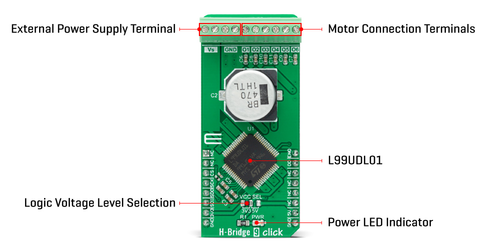
H-Bridge 9 Click is a compact add-on board that contains six MOSFET half-bridge outputs. This board features the L99UDL01, a six-channel half-bridge driver monolithic integrated circuit that is PWM configurable and current regulated from STMicroelectronics. It achieves excellent load and line regulation over a wide input supply range up to 18V. These six integrated MOSFET H-bridges are commanded entirely by the SPI interface using duration and current level commands. Complete protection features include open load, short to battery and ground, and load integrity via 10-bit current feedback. This Click board™ is suitable as a multiple brushed DC motor driver for various applications.
H-Bridge 9 Click is supported by a mikroSDK compliant library, which includes functions that simplify software development. This Click board™ comes as a fully tested product, ready to be used on a system equipped with the mikroBUS™ socket.
This product is no longer in stock
Availability date:
20%
OFF
| Company | Stock | Price |
|---|---|---|
H-Bridge 9 Click as its foundation uses the L99UDL01, a half-bridge driver that is PWM configurable and current regulated from STMicroelectronics. The device contains six MOSFET half-bridge outputs and protection and diagnostic functions designed to improve safety and simplify the design. As a complete solution, this Click board™ replaces several separate motor drivers along with their associated analog and passive components, offering at the same time a more sophisticated functionality.
The L99UDL01 can enter four different operating modes to control the working sequence: Normal mode, Sleep mode, Emergency override mode, and Standby mode as its default operation. In the Sleep mode, no-active circuitry is supplied, where logic is initialized but not operational. There is no function present in either mode to minimize the current consumption. Only wake-up circuitry is active in the Standby mode. Also, an emergency mode represents a crash override mechanism that will interrupt any current actuation command in progress and drives outputs according to the programmed values in the command and configuration registers.
Benefits are further enhanced by PWM control of the output current and sophisticated diagnostic functions that can detect over-currents, line breaks, and short circuits to the battery and ground. The load-integrity tests can also be performed without activating the load. Also, programmable current limiting gives users the ability to reduce the load, thereby increasing reliability. The output MOSFETs are fully protected with low RDS(ON) values, increasing energy efficiency and facilitating thermal management.
The L99UDL01 communicates with MCU using the standard SPI serial interface with a maximum frequency of 4MHz, supporting the most common SPI mode, SPI Mode 0. It also features an interrupt function, labeled as DO and routed to the INT pin of the mikroBUS™ socket that provides the host processor with a real-time fault indication. Besides an interrupt pin, Enable pin labeled as ENO and routed to the PWM pin of the mikroBUS™ socket enables the output functionality while held high and disables the outputs when kept low. This pin can also be used to initiate an output timed actuation, based on programmed parameters, on a rising edge.
The H-Bridge 9 Click supports an external power supply for the L99UDL01, which can be connected to the input terminal labeled as VS and should be within the range of 6V to 18V, while the DC motor coils can be connected to the terminals labeled from O1 to O6. These outputs are configured as switching drivers incorporating active re-circulation to minimize power dissipation. It also has over-current protection, under-current detection, and OFF-state diagnostics.
This Click board™ can operate with both 3.3V and 5V logic voltage levels selected via the VCC SEL jumper. This way, it is allowed for both 3.3V and 5V capable MCUs to use the SPI communication lines properly. However, the Click board™ comes equipped with a library containing easy-to-use functions and an example code that can be used, as a reference, for further development.
Type
Brushed
Applications
Can be used as a multiple brushed DC motor driver for various applications
On-board modules
L99UDL01 - multiple half-bridge driver that is PWM configurable and current regulated from STMicroelectronics
Key Features
Six integrated fully protected half bridges, several operational modes, low power consumption, high level of programming, high level diagnostics, protection features, and more
Interface
SPI
Feature
No ClickID
Compatibility
mikroBUS™
Click board size
L (57.15 x 25.4 mm)
Input Voltage
3.3V or 5V,External
This table shows how the pinout on H-Bridge 9 Click corresponds to the pinout on the mikroBUS™ socket (the latter shown in the two middle columns).
| Notes | Pin | Pin | Notes | ||||
|---|---|---|---|---|---|---|---|
| NC | 1 | AN | PWM | 16 | ENO | Enable | |
| NC | 2 | RST | INT | 15 | DO | Fault Indication | |
| SPI Chip Select | CS | 3 | CS | RX | 14 | NC | |
| SPI Clock | SCK | 4 | SCK | TX | 13 | NC | |
| SPI Data OUT | SDO | 5 | MISO | SCL | 12 | NC | |
| SPI Data IN | SDI | 6 | MOSI | SDA | 11 | NC | |
| Power Supply | 3.3V | 7 | 3.3V | 5V | 10 | 5V | Power Supply |
| Ground | GND | 8 | GND | GND | 9 | GND | Ground |
| Label | Name | Default | Description |
|---|---|---|---|
| LD1 | PWR | - | Power LED Indicator |
| JP1 | VCC SEL | Left | Logic Level Voltage Selection 3V3/5V: Left position 3V3, Right position 5V |
| Description | Min | Typ | Max | Unit |
|---|---|---|---|---|
| Supply Voltage VCC | 3.3 | - | 5 | V |
| External Supply Voltage VS | 6 | - | 18 | V |
| Operating Supply Current | - | 13 | 18 | mA |
| Operating Temperature Range | -40 | +25 | +175 | °C |
We provide a library for the H-Bridge 9 Click as well as a demo application (example), developed using MikroElektronika compilers. The demo can run on all the main MikroElektronika development boards.
Package can be downloaded/installed directly from NECTO Studio Package Manager(recommended way), downloaded from our LibStock™ or found on Mikroe github account.
Library Description
This library contains API for H-Bridge 9 Click driver.
Key functions:
hbridge9_write_register - This function writes a desired data to the selected register.hbridge9_read_register - This function reads a desired data from the selected register.hbridge9_send_actuation_pulse - This function sends an actuation pulse by toggling the ENO pin.Examples description
This example demonstrates the use of H-Bridge 9 Click board™.
void application_task ( void )
{
    hbridge9_send_actuation_pulse( &hbridge9 );
    log_printf( &logger, " Actuation pulse has been sent. rnn" );
    Delay_ms( 5000 );
}
The full application code, and ready to use projects can be installed directly from NECTO Studio Package Manager(recommended way), downloaded from our LibStock™ or found on Mikroe github account.
Other mikroE Libraries used in the example:
Additional notes and informations
Depending on the development board you are using, you may need USB UART click, USB UART 2 click or RS232 click to connect to your PC, for development systems with no UART to USB interface available on the board. The terminal available in all MikroElektronika compilers, or any other terminal application of your choice, can be used to read the message.
This Click board™ is supported with mikroSDK - MikroElektronika Software Development Kit. To ensure proper operation of mikroSDK compliant Click board™ demo applications, mikroSDK should be downloaded from the LibStock and installed for the compiler you are using.
For more information about mikroSDK, visit the official page.
NOTE: Please be advised that any peripheral devices or accessories shown connected to the Click board™ are not included in the package. Check their availability in our shop or in the YMAN section below.

$533.40

$66.50

$329.40

$239.20

$29.00

$23.20

$3.30

$2.88

$95.20

$314.30

$244.30

$244.30

$191.95

$209.30

$215.20

$199.20

$167.20
