


OFF
GO LOCAL
| Company | Stock | Price |
|---|---|---|


MIKROE-2859
23 g
Status:
GainAMP 2 click is a 6-channel programmable gain amplifier, used to amplify signals on any of the 6 non-inverting input channels up to 32x, in eight discrete steps. The gain can be set via the SPI communication interface. The click has a high signal to noise ratio, a good bandwidth, and very low gain error. These features make it an ideal solution for amplifying sensitive low signals from various sources.
This product is no longer in stock
Availability date:
OFF
| Company | Stock | Price |
|---|---|---|
Due to its low noise compared to most of the ADCs, it can be used to adjust the dynamic range of the ADC input signal. The GainAMP 2 can also be used to expand the analog input capacity of the MCU with the additional gain control for each source. This click can be easily daisy-chained if more than six inputs are needed - or to achieve other gain ratios, not possible with a single device.
GainAMP 2 click uses the MCP6S21, a rail-to-rail I/O, low noise programmable gain amplifier (PGA) from Microchip. This integrated circuit features six multiplexed non-inverting inputs, with a gain that can be programmed via the SPI interface for each input individually. The channels CH0 to CH5 are the six input channels, connected to the external signal sources. The internal multiplexer selects the channel that is gained and sent to the output pin. The gain stage of the MCP6S21 has eight different discrete steps of gain: 1, 2, 4, 5, 8, 10, 16 and 32V/V.
The rail-to-rail inputs and outputs accept voltage levels up to VCC with no distortions or phase shifting. The output voltage is offset by the resistor ladder network on the output stage and the voltage on the voltage reference pin. 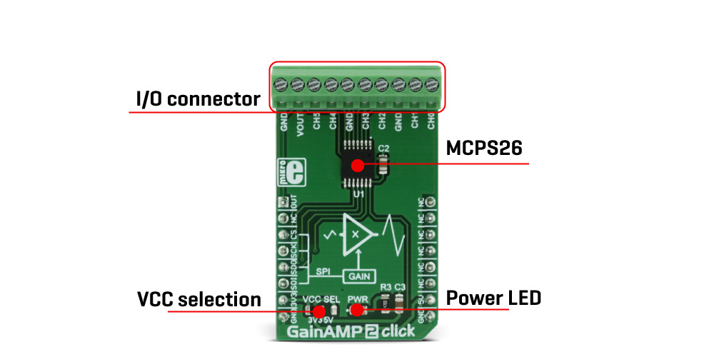
Besides the VOUT pin on the 10 pole I/O connector, the MCP6S21 output pin is also routed to the AN pin of the mikroBUS™ so it can be used as the input signal for the ADC. This allows the amplified signal to be easily digitalized and processed by the MCU. Using the click board in this configuration effectively turns the GainAMP 2 click into an analog port expander with the selectable gain on its inputs.
The MCP6S21 device can be put in a shutdown mode by setting the appropriate bits of the internal register via the SPI interface. While in shutdown mode, the power consumption is minimal. The device stays in the shutdown mode until a valid command is received via the SPI. While in the shutdown mode, device remembers states of the internal registers, so when its awaken, it will resume working as before. The internal registers can be easily accessed by using MikroElektronika library functions. More information about the registers and their settings can be found in the MCP6S21 datasheet.
GainAMP 2 click can work with both 3.3V and 5V, which can be selected by the onboard SMD jumper. GainAMP 2 click has a 10 pole I/O connector, so the connection of the external signals can be easily done.
Type
Amplifier
Applications
Used for low and sensitive signal amplification, such as the signals from various sensors, can be used as an analog input expander for a MCU or as an input amplifying stage of the ADC.
On-board modules
MCP6S26 - rail-to-rail I/O, low noise programmable gain amplifier
Key Features
Six multiplexed non-inverting analog input channels, with programmable gain, rail-to-rail inputs and outputs with no phase shifting and very good bandwidth, low THD, and great SNR
Interface
Analog,SPI
Feature
No ClickID
Compatibility
mikroBUS™
Click board size
M (42.9 x 25.4 mm)
Input Voltage
3.3V or 5V
This table shows how the pinout on GainAMP 2 click corresponds to the pinout on the mikroBUS™ socket (the latter shown in the two middle columns).
| Notes | Pin | Pin | Notes | ||||
|---|---|---|---|---|---|---|---|
| Signal Output | VOUT | 1 | AN | PWM | 16 | NC | |
| NC | 2 | RST | INT | 15 | NC | ||
| SPI Chip Select | CS | 3 | CS | RX | 14 | NC | |
| SPI Clock | SCK | 4 | SCK | TX | 13 | NC | |
| SPI Slave Data Out | SDO | 5 | MISO | SCL | 12 | NC | |
| SPI Slave Data In | SDI | 6 | MOSI | SDA | 11 | NC | |
| Power Supply | +3.3V | 7 | 3.3V | 5V | 10 | +5V | Power supply |
| Ground | GND | 8 | GND | GND | 9 | GND | Ground |
| Description | Min | Typ | Max | Unit |
|---|---|---|---|---|
| Input voltage range | -0.3 | VCC+0.3 | V | |
| Frequency response (-3dB) | 2 | 12 | MHz | |
| Total harmonic distortion (THD) | 0.0015 | 0.036 | % | |
| Maximum SPI SCK frequency | 10 | MHz |
| Label | Name | Default | Description |
|---|---|---|---|
| LD1 | PWR | - |
Power LED indicator
|
| JP1 | VCC SEL | 3V3 | Power supply voltage selection: Left position 3V3, right position 5V |
| CN1 | CN1 | - | I/O connector |
| Label | Name |
|---|---|
| PIN1 | Input channel 0 |
| PIN2 | Input channel 1 |
| PIN4 | Input channel 2 |
| PIN5 | Input channel 3 |
| PIN7 | Input channel 4 |
| PIN8 | Input channel 5 |
| PIN9 | Output |
| PIN3, PIN6, PIN10 | GND |
We provide a library for the GainAMP 2 Click as well as a demo application (example), developed using MIKROE compilers. The demo can run on all the main MIKROE development boards.
Package can be downloaded/installed directly from NECTO Studio Package Manager (recommended), downloaded from our LibStock™ or found on MIKROE github account.
Library Description
This library contains API for GainAMP 2 Click driver.
Key functions
Set the channel gain.
Return voltage measured from VOUT pin.
Send Command
Example Description
This application is programmable gain amplifier
 void application_task ( void )
 {
     log_printf( &logger,"Voltage at VOUT: %f rn", gainamp2_get_voltage( &gainamp2 ) );
     log_printf( &logger,"------------------------------- rn " );
     Delay_ms ( 1000 );
 }
The full application code, and ready to use projects can be installed directly from NECTO Studio Package Manager (recommended), downloaded from our LibStock™ or found on MIKROE github account.
Other MIKROE Libraries used in the example:
Additional notes and informations
Depending on the development board you are using, you may need USB UART click, USB UART 2 Click or RS232 Click to connect to your PC, for development systems with no UART to USB interface available on the board. UART terminal is available in all MIKROE compilers.
This Click board™ is supported with mikroSDK - MIKROE Software Development Kit. To ensure proper operation of mikroSDK compliant Click board™ demo applications, mikroSDK should be downloaded from the LibStock and installed for the compiler you are using.
For more information about mikroSDK, visit the official page.
NOTE: Please be advised that any peripheral devices or accessories shown connected to the Click board™ are not included in the package. Check their availability in our shop or in the YMAN section below.

$889.00

$95.00

$549.00

$299.00

$29.00

$29.00

$3.30

$3.60

$119.00

$449.00

$349.00

$349.00

$349.00

$299.00

$269.00

$249.00

$209.00
