


OFF
GO LOCAL
| Company | Stock | Price |
|---|---|---|


MIKROE-4887
23 g
Status:
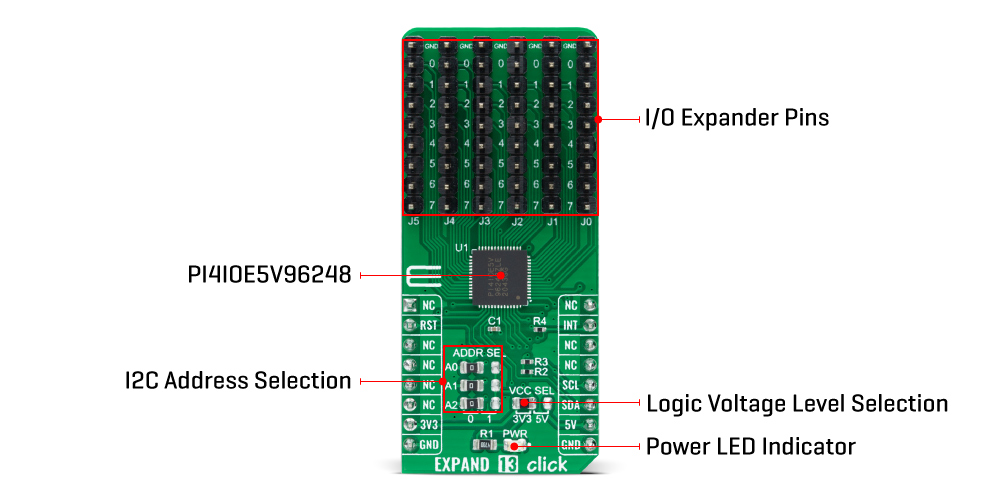
Expand 13 Click is a compact add-on board that contains a multi-port I/O expander. This board features the PI4IOE5V96248, a 48-bit general-purpose I/O expander providing remote I/O expansion for most MCU’s families from Diodes Incorporated. The PI4IOE5V96248 comes in a 6-channel configuration and allows easy addition of I/O through a standard I2C serial interface. It has a built-in level shifting feature that makes it highly flexible in power supply systems where communication between incompatible I/O voltages is required. It also contains a reset and interrupts feature that informs the MCU of incoming data on its ports without communicating via the serial bus. This Click board™ provides a simple solution when additional I/Os are needed while keeping interconnections to a minimum in system monitoring applications, industrial controllers, portable equipment, and many more.
Expand 13 Click is supported by a mikroSDK compliant library, which includes functions that simplify software development. This Click board™ comes as a fully tested product, ready to be used on a system equipped with the mikroBUS™ socket.
This product is no longer in stock
Availability date:
OFF
| Company | Stock | Price |
|---|---|---|
Expand 13 Click as its foundation uses the PI4IOE5V96248, a 48-bit low-voltage translating general-purpose remote I/O expander from Diodes Incorporated. This port expander is a simple solution when additional I/Os are needed while keeping interconnections to a minimum, particularly great for system monitoring applications, industrial controllers, portable equipment, and others. The PI4IOE5V96248 comes in a 6-channel configuration and has a built-in level shifting feature that makes it highly flexible in power supply systems where communication between incompatible I/O voltages is required.
The PI4IOE5V96248 has low current consumption and includes latched outputs with high current drive capability for directly driving LEDs. All ports of the PI4IOE5V96248 are entirely independent and can be used either as input or output ports without using a control signal for data directions. Input data is transferred from the ports to the MCU in the Read mode, while output data transmits to the ports in the Write mode, where every data transmission must consist of a multiple of six bytes.
Expand 13 Click communicates with MCU using the standard I2C 2-Wire interface to read data and configure settings with a maximum frequency of 1MHz. Besides, it also allows the choice of the least significant bit of its I2C slave address by positioning the SMD jumpers labeled as ADDR SEL to an appropriate position marked as 0 and 1. This way, the PI4IOE5V96248 provides the opportunity of the 64 possible different I2C addresses by positioning the SMD jumper to an appropriate position. In addition to I2C communication, two GPIO pins connected to the mikroBUS™ socket pins are also used.
The Reset pin, routed to the RST pin of the mikroBUS™ socket, is used to place the PI4IOE5V96248 registers in their default state, while the interrupt, routed to the INT pin of the mikroBUS™ socket, may be configured as an interrupt to notify the host MCU of incoming data on any port without having to communicate via the I2C-bus.
This Click board™ can operate with both 3.3V and 5V logic voltage levels selected via the VCC SEL jumper. This way, it is allowed for both 3.3V and 5V capable MCUs to use the I2C communication lines properly. However, the Click board™ comes equipped with a library containing easy-to-use functions and an example code that can be used, as a reference, for further development.
Type
Port expander
Applications
Can be used in system monitoring applications, industrial controllers, portable equipment, and many more
On-board modules
PI4IOE5V96248 - 48-bit low-voltage translating general-purpose remote I/O expander from Diodes Incorporated
Key Features
Remote I/O pins that default to inputs at Power-Up, compliant with the I2C-bus Fast and Standard modes, 5V tolerant I/Os, 25mA sink capability for directly driving LEDs, programmable slave addresses, and more
Interface
I2C
Feature
No ClickID
Compatibility
mikroBUS™
Click board size
L (57.15 x 25.4 mm)
Input Voltage
3.3V or 5V
This table shows how the pinout on Expand 13 Click corresponds to the pinout on the mikroBUS™ socket (the latter shown in the two middle columns).
| Notes | Pin | Pin | Notes | ||||
|---|---|---|---|---|---|---|---|
| NC | 1 | AN | PWM | 16 | NC | ||
| Reset | RST | 2 | RST | INT | 15 | INT | Interrupt |
| NC | 3 | CS | RX | 14 | NC | ||
| NC | 4 | SCK | TX | 13 | NC | ||
| NC | 5 | MISO | SCL | 12 | SCL | I2C Clock | |
| NC | 6 | MOSI | SDA | 11 | SDA | I2C Data | |
| Power Supply | 3.3V | 7 | 3.3V | 5V | 10 | 5V | Power Supply |
| Ground | GND | 8 | GND | GND | 9 | GND | Ground |
| Label | Name | Default | Description |
|---|---|---|---|
| LD1 | PWR | - | Power LED Indicator |
| JP1 | VCC SEL | Left | Logic Level Voltage Selection 3V3/5V: Left position 3V3, Right position 5V |
| JP2-JP4 | ADDR SEL | Left | I2C Address Selection 0/1: Left position 0, Right position 1 |
| J0-J5 | J0-J5 | Populated | I/O Expander Ports |
| Description | Min | Typ | Max | Unit |
|---|---|---|---|---|
| Supply Voltage | 3.3 | - | 5 | V |
| Maximum Output Current | - | - | 50 | mA |
| Number of I/Os | - | - | 48 | pins |
| Operating Temperature Range | -40 | +25 | +85 | °C |
We provide a library for the Expand 13 Click as well as a demo application (example), developed using MikroElektronika compilers. The demo can run on all the main MikroElektronika development boards.
Package can be downloaded/installed directly from NECTO Studio Package Manager(recommended way), downloaded from our LibStock™ or found on Mikroe github account.
Library Description
This library contains API for Expand 13 Click driver.
Key functions
expand13_enable_device This function enables the device by setting the RST pin to high logic state.
expand13_write_all_ports This function writes a desired data to all 6 ports.
expand13_read_all_ports This function reads the state of all 6 ports.
Example Description
This example demonstrates the use of Expand 13 Click board™, by writing data to all six ports and then reading back the status of the ports.
 void application_task ( void )
 {
     uint8_t port_value[ 6 ] = { 0 };
     uint16_t pin_num = 0;

     for ( pin_num = EXPAND13_PIN_0_MASK; pin_num <= EXPAND13_PIN_7_MASK; pin_num <<= 1 )
     {
         if ( !expand13_get_int_pin ( &expand13 ) )
         {
             log_printf( &logger, " External input has occurred.rn" );
         }

         memset ( port_value, pin_num, 6 );
         expand13_write_all_ports( &expand13, port_value );

         expand13_read_all_ports( &expand13, port_value );
         for ( uint8_t cnt = EXPAND13_PORT_0; cnt <= EXPAND13_PORT_5; cnt++ )
         {
             log_printf( &logger, " Status port %d : 0x%.2Xrn", ( uint16_t ) cnt, ( uint16_t ) port_value[ cnt ] );
         }
         log_printf( &logger, "n" );
         Delay_ms( 1000 );
     }
 }
The full application code, and ready to use projects can be installed directly from NECTO Studio Package Manager(recommended way), downloaded from our LibStock™ or found on Mikroe github account.
Other Mikroe Libraries used in the example:
Additional notes and informations
Depending on the development board you are using, you may need USB UART click, USB UART 2 Click or RS232 Click to connect to your PC, for development systems with no UART to USB interface available on the board. UART terminal is available in all MikroElektronika compilers.
This Click board™ is supported with mikroSDK - MikroElektronika Software Development Kit. To ensure proper operation of mikroSDK compliant Click board™ demo applications, mikroSDK should be downloaded from the LibStock and installed for the compiler you are using.
For more information about mikroSDK, visit the official page.
NOTE: Please be advised that any peripheral devices or accessories shown connected to the Click board™ are not included in the package. Check their availability in our shop or in the YMAN section below.

$889.00

$95.00

$549.00

$299.00

$29.00

$29.00

$6.59

$3.60

$119.00

$349.00

$349.00

$299.00

$449.00

$349.00

$269.00

$249.00

$209.00
