


OFF
GO LOCAL
| Company | Stock | Price |
|---|---|---|


MIKROE-5318
18 g
Status:
DIGI POT 11 Click is a compact add-on board representing a digitally controlled potentiometer. This board features a double pack of the MAX5387, a dual, 256-tap, volatile, low-voltage linear taper digital potentiometer from Analog Devices. This way, four digitally I2C-controlled potentiometers are realized with end-to-end resistance values of 50kΩ. Operating from a single +3.3V power supply, this device provides a low 35ppm/ºC end-to-end temperature coefficient. This Click board™ can be used as a mechanical potentiometer replacement for the portable consumer market and battery-backup industrial applications.
DIGI POT 11 Click is supported by a mikroSDK compliant library, which includes functions that simplify software development. This Click board™ comes as a fully tested product, ready to be used on a system equipped with the mikroBUS™ socket.
This product is no longer in stock
Availability date:
OFF
| Company | Stock | Price |
|---|---|---|
DIGI POT 11 Click as its foundation uses a double pack of the MAX5387, a dual volatile, low-voltage linear taper digital potentiometer from Analog Devices, with which four digitally controlled potentiometers are realized with end-to-end resistance values of 50kΩ. The potentiometers consist of 255 fixed resistors in series between appropriate H and L terminals, providing a low 35ppm/ºC end-to-end temperature coefficient. The potentiometer wiper (W) terminals are programmable to access any one of the 256 tap points on the resistor string.
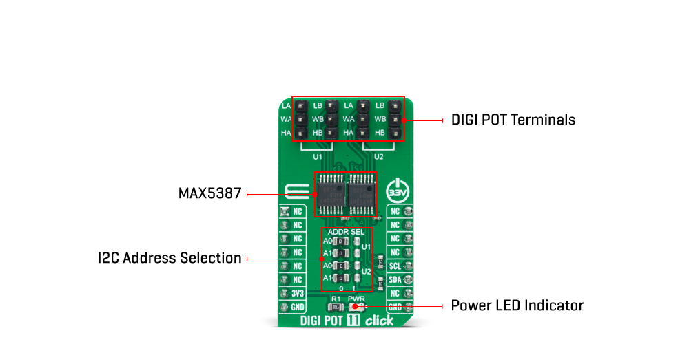
This Click board™ communicates with MCU using the standard I2C 2-Wire interface with a maximum clock frequency of 400kHz. The potentiometers are programmable independently of each other. The MAX5387 has a 7-bit slave address with the first five MSBs fixed to 01010. The address pins A0 and A1 of both potentiometers are programmed by the user and determine the value of the last three LSBs of the slave address, which can be selected by positioning onboard SMD jumpers labeled as ADDR SEL, in U1 or U2 part, to an appropriate position marked as 0 or 1.
The I2C interface contains a shift register that decodes the command and addresses bytes, routing the data to the appropriate control registers. Data written to a control register immediately updates the wiper position. In the beginning, wipers A and B always power up in mid-position.
This Click board™ can be operated only with a 3.3V logic voltage level. The board must perform appropriate logic voltage level conversion before using MCUs with different logic levels. However, the Click board™ comes equipped with a library containing functions and an example code that can be used, as a reference, for further development.
Type
Digital potentiometer
Applications
Can be used as a mechanical potentiometer replacement for the portable consumer market and battery-backup industrial applications
On-board modules
MAX5387 - dual volatile linear taper digital potentiometer from Analog Devices
Key Features
Double dual potentiometers, 256-tap linear taper positions, single 3.3V supply, low power consumption, 50kΩ end-to-end resistance, I2C interface, Power-On sets wiper to midscale, and more
Interface
I2C
Feature
No ClickID
Compatibility
mikroBUS™
Click board size
M (42.9 x 25.4 mm)
Input Voltage
3.3V
This table shows how the pinout on DIGI POT 11 Click corresponds to the pinout on the mikroBUS™ socket (the latter shown in the two middle columns).
| Notes | Pin | Pin | Notes | ||||
|---|---|---|---|---|---|---|---|
| NC | 1 | AN | PWM | 16 | NC | ||
| NC | 2 | RST | INT | 15 | NC | ||
| NC | 3 | CS | RX | 14 | NC | ||
| NC | 4 | SCK | TX | 13 | NC | ||
| NC | 5 | MISO | SCL | 12 | SCL | I2C Clock | |
| NC | 6 | MOSI | SDA | 11 | SDA | I2C Data | |
| Power Supply | 3.3V | 7 | 3.3V | 5V | 10 | NC | |
| Ground | GND | 8 | GND | GND | 9 | GND | Ground |
| Label | Name | Default | Description |
|---|---|---|---|
| LD1 | PWR | - | Power LED Indicator |
| JP1-JP4 | ADDR SEL | Left | I2C Address Selection 0/1: Left position 0, Right position 1 |
| J1-J4 | U1-U2 | Populated | DIGI POT Header Terminals |
| Description | Min | Typ | Max | Unit |
|---|---|---|---|---|
| Supply Voltage | - | 3.3 | - | V |
| End-to-end Resistance | - | - | 50 | kΩ |
| Number of Steps | - | - | 256 | step |
| Operating Temperature Range | -40 | +25 | +120 | °C |
We provide a library for the DIGI POT 11 Click as well as a demo application (example), developed using MikroElektronika compilers. The demo can run on all the main MikroElektronika development boards.
Package can be downloaded/installed directly from NECTO Studio Package Manager(recommended way), downloaded from our LibStock™ or found on Mikroe github account.
Library Description
This library contains API for DIGI POT 11 Click driver.
Key functions
digipot11_set_u1_wiper This function sets the position of the selected wiper of U1 device by using I2C serial interface.
digipot11_set_u2_wiper This function sets the position of the selected wiper of U2 device by using I2C serial interface.
Example Description
This example demonstrates the use of DIGI POT 11 Click board™ by changing the wipers position of both U1 and U2 devices.
void application_task ( void )
 {
     for ( uint16_t wiper_pos = DIGIPOT11_WIPER_ZERO_SCALE; wiper_pos <= DIGIPOT11_WIPER_FULL_SCALE; wiper_pos += 5 )
     {
         if ( DIGIPOT11_OK == digipot11_set_u1_wiper ( &digipot11, DIGIPOT11_WIPER_SEL_BOTH, ( uint8_t ) wiper_pos ) )
         {
             log_printf( &logger, " U1 wipers position: %urn", wiper_pos );
         }
         if ( DIGIPOT11_OK == digipot11_set_u2_wiper ( &digipot11, DIGIPOT11_WIPER_SEL_BOTH,
                                                       ( uint8_t ) ( DIGIPOT11_WIPER_FULL_SCALE - wiper_pos ) ) )
         {
             log_printf( &logger, " U2 wipers position: %urnn", ( DIGIPOT11_WIPER_FULL_SCALE - wiper_pos ) );
         }
         Delay_ms( 1000 );
     }
 }
The full application code, and ready to use projects can be installed directly from NECTO Studio Package Manager(recommended way), downloaded from our LibStock™ or found on Mikroe github account.
Other Mikroe Libraries used in the example:
Additional notes and informations
Depending on the development board you are using, you may need USB UART click, USB UART 2 Click or RS232 Click to connect to your PC, for development systems with no UART to USB interface available on the board. UART terminal is available in all MikroElektronika compilers.
This Click board™ is supported with mikroSDK - MikroElektronika Software Development Kit. To ensure proper operation of mikroSDK compliant Click board™ demo applications, mikroSDK should be downloaded from the LibStock and installed for the compiler you are using.
For more information about mikroSDK, visit the official page.
NOTE: Please be advised that any peripheral devices or accessories shown connected to the Click board™ are not included in the package. Check their availability in our shop or in the YMAN section below.

$889.00

$95.00

$549.00

$299.00

$29.00

$29.00

$3.30

$3.60

$119.00

$449.00

$349.00

$349.00

$349.00

$299.00

$269.00

$249.00

$209.00
