


OFF
GO LOCAL
| Company | Stock | Price |
|---|---|---|


MIKROE-6595
18 g
Status:
DC Motor 30 Click is a compact add-on board designed for intelligent control of brushed DC motors in embedded applications. It is based on the DRV8235 motor driver from Texas Instruments, a high-performance N-channel H-bridge driver with integrated speed regulation and stall detection. This Click board supports a wide input voltage range from 4.5V to 38V and delivers up to 2A RMS (3.7A peak) motor current. It features both PH/EN and 400kHz I2C control interfaces, along with integrated current sensing, current limiting, fault indication, and a SLEEP mode for ultra-low power operation. DC Motor 30 Click is ideal for use in printers, vacuum robots, washers, dryers, hospital beds, POS printers, and other devices requiring reliable and adaptive brushed DC motor control.
DC Motor 30 Click is fully compatible with the mikroBUS™ socket and can be used on any host system supporting the mikroBUS™ standard. It comes with the mikroSDK open-source libraries, offering unparalleled flexibility for evaluation and customization. What sets this Click board™ apart is the groundbreaking ClickID feature, enabling your host system to automatically detect and identify this add-on board.
This product is no longer in stock
Availability date:
OFF
| Company | Stock | Price |
|---|---|---|
DC Motor 30 Click is based on the DRV8235 motor driver from Texas Instruments. This driver combines a full N-channel H-bridge configuration with built-in speed regulation, stall detection, current sensing, and a wide array of protection features, making it suitable for various precision-driven applications such as printers, vacuum robots, washers and dryers, coffee machines, POS printers, hospital bed and bed control systems, and fitness machines. The DRV8235 supports a broad supply voltage range from 4.5V to 38V provided through the INPUT terminal and is capable of delivering up to 2A RMS continuous current, with peak current reaching 3.7A on the LOAD terminal, ensuring compatibility with a wide range of brushed DC motors in compact or power-sensitive systems.
At the heart of DC Motor 30 Click lies the DRV8235’s integrated speed regulation capability, which allows the system to maintain a consistent motor speed across varying supply voltages and changing mechanical loads. By leveraging real-time voltage and current feedback from the motor, this feature eliminates the need for external speed sensors, reducing system complexity. The speed regulation not only ensures smooth operation but also contributes to long-term power savings and reduced thermal stress on system components. Furthermore, the device implements a soft-start and soft-stop mechanism, providing controlled motor ramp-up and shutdown that mitigates large inrush currents and mechanical stress, thus protecting motor windings and increasing system reliability.
DC Motor 30 Click features dual control modes to accommodate various system requirements. The traditional PH/EN interface using IN1 and IN2 pins allows direct control of the H-bridge’s operation, which is built from four low-resistance N-channel MOSFETs with a typical RDS(ON) of 600mΩ (combined for high-side and low-side FETs). Additionally, the board supports a 400kHz I2C communication interface, enabling access to a set of programmable registers that provide advanced diagnostics, stall detection settings, and current limit configuration. Stall detection is based on real-time current monitoring using the IP pin, which outputs a current-sense signal proportional to the motor current. This feedback is also used for monitoring during drive and brake/slow-decay states, allowing the host MCU to assess motor behavior in various operating conditions. The current regulation feature, configured via the VREF trimmer and IP feedback, ensures the motor current stays within a safe predefined limit, further enhancing control precision and safety.
The DRV8235 integrates multiple protection features to ensure safe operation under fault conditions. These include undervoltage lockout (UVLO), overcurrent protection (OCP), thermal shutdown (TSD), and overvoltage protection (OVP). The FLT pin, in a combination with a red FAULT LED on the board, provides immediate visual feedback of any active fault, aiding in quick diagnostics and system troubleshooting. The overvoltage protection function is particularly crucial when the motor is manually rotated while the driver is disabled or in sleep mode, as it automatically engages the brake state to suppress back EMF-induced voltages that could otherwise damage sensitive electronics.
To further support energy-efficient operation, the board includes a SLEEP switch that toggles the DRV8235 between active and ultra-low power standby mode. In the left (0) position, the switch places the device into sleep mode, significantly reducing current consumption during system inactivity. In the right (1) position, the device is fully enabled and ready to drive the motor.
This Click board™ can operate with either 3.3V or 5V logic voltage levels selected via the VCC SEL jumper. This way, both 3.3V and 5V capable MCUs can use the communication lines properly. Also, this Click board™ comes equipped with a library containing easy-to-use functions and an example code that can be used as a reference for further development.
Type
Brushed
Applications
Ideal for use in printers, vacuum robots, washers, dryers, hospital beds, POS printers, and other devices requiring reliable and adaptive brushed DC motor control
On-board modules
DRV8235 - N-channel H-bridge motor driver from Texas Instruments
Key Features
Integrated speed and voltage regulation, stall detection, current sensing and regulation, PH/EN control interface, 400kHz I2C communication interface, programmable registers for diagnostics and configuration, fault indication, soft-start and soft-stop functionality, protection features, ultra-low power sleep mode with manual switch control, and more
Interface
GPIO,I2C
Feature
ClickID
Compatibility
mikroBUS™
Click board size
M (42.9 x 25.4 mm)
Input Voltage
3.3V or 5V,External
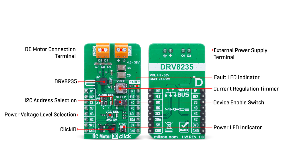
This table shows how the pinout on DC Motor 30 Click corresponds to the pinout on the mikroBUS™ socket (the latter shown in the two middle columns).
| Notes | Pin | Pin | Notes | ||||
|---|---|---|---|---|---|---|---|
| Analog Current Output | IP | 1 | AN | PWM | 16 | IN2 | H-Bridge Control |
| H-Bridge Control | IN2 | 2 | RST | INT | 15 | FLT | Fault Indication |
| ID COMM | CS | 3 | CS | RX | 14 | NC | |
| NC | 4 | SCK | TX | 13 | NC | ||
| NC | 5 | MISO | SCL | 12 | SCL | I2C Clock | |
| NC | 6 | MOSI | SDA | 11 | SDA | I2C Data | |
| Power Supply | 3.3V | 7 | 3.3V | 5V | 10 | 5V | Power Supply |
| Ground | GND | 8 | GND | GND | 9 | GND | Ground |
| Label | Name | Default | Description |
|---|---|---|---|
| LD1 | PWR | - | Power LED Indicator |
| LD2 | FAULT | - | Fault LED Indicator |
| JP1 | VCC SEL | Left | Power Voltage Level Selection 3V3/5V: Left position 3V3, Right position 5V |
| SW1 | SLEEP | Right | Device Enable Switch 0/1: Left position 0, Right position 1 |
| JP3-JP4 | ADDR SEL | Left | I2C Address Selection 0/1: Left position 0, Right position 1 |
| P1 | VREF | - | Current Regulation Switch |
| Description | Min | Typ | Max | Unit |
|---|---|---|---|---|
| Supply Voltage | 3.3 | - | 5 | V |
| External Power Supply Voltage | 4.5 | - | 38 | V |
| Output Current (RMS) | - | - | 2 | A |
| Output Current (Peak) | - | - | 3.7 | A |
DC Motor 30 Click demo application is developed using the NECTO Studio, ensuring compatibility with mikroSDK's open-source libraries and tools. Designed for plug-and-play implementation and testing, the demo is fully compatible with all development, starter, and mikromedia boards featuring a mikroBUS™ socket.
Example Description
This example demonstrates the control of a DC motor using the DC Motor 30 Click board. It performs motor driving in different modes (forward, brake, reverse, and coast) and periodically reads the output current and fault status.
Key Functions
dcmotor30_cfg_setup This function initializes Click configuration structure to initial values.dcmotor30_init This function initializes all necessary pins and peripherals used for this Click board.dcmotor30_default_cfg This function executes a default configuration of DC Motor 30 Click board.dcmotor30_drive_motor This function drives the motor in the selected PWM control mode state.dcmotor30_get_out_current This function reads the current output measurement in mA.Application Init
Initializes the logger and the Click board driver, then sets the default configuration.
Application Task
Drives the motor in different states and monitors the current consumption and possible fault conditions.
Application Output
This Click board can be interfaced and monitored in two ways:
Additional Notes and Information
The complete application code and a ready-to-use project are available through the NECTO Studio Package Manager for direct installation in the NECTO Studio. The application code can also be found on the MIKROE GitHub account.
NOTE: Please be advised that any peripheral devices or accessories shown connected to the Click board™ are not included in the package. Check their availability in our shop or in the YMAN section below.

$14.40

$889.00

$95.00

$549.00

$299.00

$29.00

$29.00

$6.59

$3.60

$119.00

$449.00

$349.00

$349.00

$349.00

$299.00

$269.00

$249.00

$209.00
