


OFF
GO LOCAL
| Company | Stock | Price |
|---|---|---|


MIKROE-950
28 g
Status:
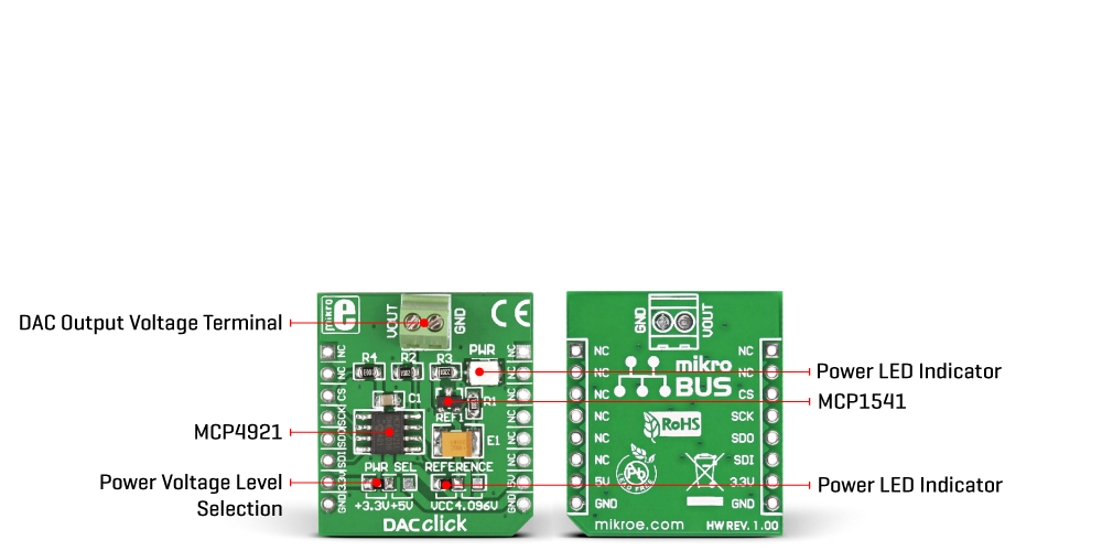
DAC Click is a compact add-on board with a fully-featured, highly accurate digital-to-analog converter. This board features the MCP4921, a 12-bit DAC with an SPI interface from Microchip. The MCP4921 has a rail-to-rail output, low power consumption, and fast setting time over a single channel. The DAC Click also has the MCP1541, a 4.096V voltage reference from Microchip, to provide an external optional reference voltage to the MCP4921 DAC chip. This Click board™ makes the perfect solution for offset and gain control applications, VCO tuning, programmable reference, and more.
DAC Click is supported by a mikroSDK compliant library, which includes functions that simplify software development. This Click board™ comes as a fully tested product, ready to be used on a system equipped with the mikroBUS™ socket.
This product is no longer in stock
Availability date:
OFF
| Company | Stock | Price |
|---|---|---|
DAC Click is based on the MCP4921, a 12-bit DAC with an SPI interface from Microchip. It utilizes a resistive string architecture, with its inherent advantages of low DNL error, low ratio metric temperature coefficient, and fast settling time over an extended temperature range. The analog output is provided on the VOUT screw terminal. The VOUT can swing from approximately 0V to approximately VCC voltage, in the case of this Click board™, 3.3V or 5V. The analog signal on the reference pin of the MCP4921 is utilized to set the reference voltage on the string DAC. The reference voltage can be selected between the VCC and the 4.096V given by the MCP1541 via the REF SEL jumper.
DAC Click uses the SPI serial interface over the mikroBUS™ socket to communicate with the host MCU, with 20MHz clock support. The 12-bit data is sent to the DAC through the SPI interface. This interface is also used to enter the Shutdown mode, during which the supply current is isolated from most of the internal circuitry. The Power-on-Reset (POR) circuit allows the device to continue to have a high-impedance output until a valid command is performed to the DAC registers, thus ensuring a reliable power-up.
This Click board™ can operate with either 3.3V or 5V logic voltage levels selected via the PWR SEL jumper. This way, both 3.3V and 5V capable MCUs can use the communication lines properly. However, the Click board™ comes equipped with a library containing easy-to-use functions and an example code that can be used, as a reference, for further development.
Type
DAC
Applications
Can be used for offset and gain control applications, VCO tuning, programmable reference, and more
On-board modules
MCP4921 - DAC with an SPI interface from Microchip
Key Features
12-bit output voltage resolution, rail-to-rail output, selectable reference voltage, Power-Down mode, low power consumption, SPI interface, fast output setting time, and more
Interface
SPI
Feature
No ClickID
Compatibility
mikroBUS™
Click board size
S (28.6 x 25.4 mm)
Input Voltage
3.3V or 5V
This table shows how the pinout on DAC Click corresponds to the pinout on the mikroBUS™ socket (the latter shown in the two middle columns).
| Notes | Pin | Pin | Notes | ||||
|---|---|---|---|---|---|---|---|
| NC | 1 | AN | PWM | 16 | NC | ||
| NC | 2 | RST | INT | 15 | NC | ||
| SPI Chip Select | CS | 3 | CS | RX | 14 | NC | |
| SPI Clock | SCK | 4 | SCK | TX | 13 | NC | |
| SPI Data OUT | SDO | 5 | MISO | SCL | 12 | NC | |
| SPI Data IN | SDI | 6 | MOSI | SDA | 11 | NC | |
| Power Supply | 3.3V | 7 | 3.3V | 5V | 10 | 5V | Power Supply |
| Ground | GND | 8 | GND | GND | 9 | GND | Ground |
| Label | Name | Default | Description |
|---|---|---|---|
| - | PWR | - | Power LED Indicator |
| J2 | PWR SEL | Left | Logic Level Voltage Selection 3V3/5V: Left position 3V3, Right position 5V |
| J1 | REFERENCE | Left | Reference Voltage Selection VCC/4.096V: Left position VCC, Right position 4.096V |
| Description | Min | Typ | Max | Unit |
|---|---|---|---|---|
| Supply Voltage | 3.3 | - | 5 | V |
| Resolution | - | 12 | - | bit |
We provide a library for the DAC Click as well as a demo application (example), developed using MIKROE compilers. The demo can run on all the main MIKROE development boards.
Package can be downloaded/installed directly from NECTO Studio Package Manager (recommended), downloaded from our LibStock™ or found on Mikroe github account.
Library Description
This library contains API for DAC Click driver.
Key functions
This function is used to set output voltage in percents.
This function is used to set output voltage.
Example Description
This demo example sends digital signal to the outputs and converts it to analog.
 void application_task ( void )
 {
     for ( dac_val = 0; dac_val <= DAC_RESOLUTION; dac_val += DAC_STEP_VALUE )
     {
         dac_set_voltage( &dac, dac_val );
         dac_val *= DAC_CALIB_VAL_1;
         dac_val /= DAC_CALIB_VAL_2;
         log_printf( &logger, " Current DAC Value: %d mV rn", dac_val );

         log_printf( &logger, "----------------------------------rn" );

         Delay_ms( 2000 );
     }
 }
The full application code, and ready to use projects can be installed directly from NECTO Studio Package Manager (recommended), downloaded from our LibStock™ or found on Mikroe github account.
Other Mikroe Libraries used in the example:
Additional notes and informations
Depending on the development board you are using, you may need USB UART click, USB UART 2 Click or RS232 Click to connect to your PC, for development systems with no UART to USB interface available on the board. UART terminal is available in all MIKROE compilers.
This Click board™ is supported with mikroSDK - MIKROE Software Development Kit. To ensure proper operation of mikroSDK compliant Click board™ demo applications, mikroSDK should be downloaded from the LibStock and installed for the compiler you are using.
For more information about mikroSDK, visit the official page.
NOTE: Please be advised that any peripheral devices or accessories shown connected to the Click board™ are not included in the package. Check their availability in our shop or in the YMAN section below.

$889.00

$95.00

$549.00

$299.00

$29.00

$29.00

$3.30

$3.60

$119.00

$449.00

$349.00

$349.00

$349.00

$299.00

$269.00

$249.00

$209.00
