


OFF
GO LOCAL
| Company | Stock | Price |
|---|---|---|


MIKROE-3886
19 g
Status:
DAC 7 click carries the AD5624R, a low-power four-channel, 12-bit buffered Digital-to-Analog Converter. AD5624R converts digital value to the corresponding voltage level using external voltage reference. This will help you convert digital information from the main board to four analog outputs on the DAC 7 click. For that purpose, DAC 7 click uses MCP1541, which is a low-dropout precision voltage reference with 4.096V output voltage. With all those possibilities on board, DAC 7 click makes a perfect choice for an accurate and simple generation of analog signals for various purposes, such as programmable Power Supplies, Laser Drivers, Projectors, IP Network cameras, auto focus digital still camera lens, and more.
DAC 7 click board™ is supported by a mikroSDK compliant library, which includes functions that simplify software development. This Click board™ comes as a fully tested product, ready to be used on a system equipped with the mikroBUS™ socket.
This product is no longer in stock
Availability date:
OFF
| Company | Stock | Price |
|---|---|---|
DAC 7 click is an advanced 12-bit, four-channel digital to analog converter (DAC). This device communicates with the main MCU through the is compatible with standard SPI, QSPI™, MICROWIRE™, and DSP interface standards. Also, there is a selectable voltage reference as well with onboard jumpers which makes this click more open for specific projects.
The main active component on DAC 7 click board is AD5624R from Analog Devices. This is a low power, four channel, 12-bit voltage output Digital-To-Analog Convertor (DAC). It is specified monotonic by design across a wide power supply range from 2.7 V to 5.5 V. Using an external reference, the AD5624R provides a full-scale output voltage in the range from 0V to Vref, while consuming 0.1 mA quiescent current per channel. The AD5624R also includes per channel, user programmable, power down registers facilitate the DAC output buffers to start in a power down to 10K state and remain in this state until a power up command is issued to these output buffers.
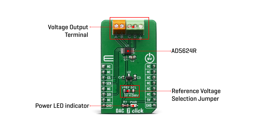
The DAC 7 click has a high precision voltage reference included onboard. For that purpose we have used 4.096V precision voltage reference MCP1541 from Microchip. This little SOT23 device is stable with capacitive loads. It has regulations for both sink and source and is very accurate. This gives DAC 7 click good flexibility for use in various applications.
Low quiescent current, wide power supply range, and per channel power down option makes AD5624R ideal for low power, battery operated system. The device communicates through SPI interface. Besides the standard SPI, QSPI™, MICROWIRE™, and DSP interface standards are also supported. However, this click board™ is using standard SPI communication with the main MCU.
The reference voltage level can be selected via VREF SEL jumper, between 4.096V and 5V. This allows for both 4.096V and 5V Voltage outputs from DAC 7 click can be connected through 9-therminal block where first is common GND and the last eight are VOUTA to VOUTH.
This Click Board™ is designed to be operated only with 5V logic level. A proper logic voltage level conversion should be performed before the Click board™ is used with MCUs with logic levels of 3.3V.
Type
DAC
Applications
Suitable for programmable power supplies, programable window comparator, VCOM biasing in display panel, laser driver in multifunction printers, auto focus digital still camera lens, ATM machines, currency counters, barcode readers, IP network cameras, projectors
On-board modules
AD5624R- a low power, four channel, 12-bit voltage output Digital-To-Analog Convertor (DAC) from Analog Devices; and MCP1541 - a 4.096V precision voltage reference IC, from Microchip.
Key Features
High precision voltage reference, low power consumption, high speed SPI interface, 12bit resolution, reference voltage selection
Interface
SPI
Feature
No ClickID
Compatibility
mikroBUS™
Click board size
M (42.9 x 25.4 mm)
Input Voltage
5V
This table shows how the pinout on DAC 7 click corresponds to the pinout on the mikroBUS™ socket (the latter shown in the two middle columns).
| Notes | Pin | Pin | Notes | ||||
|---|---|---|---|---|---|---|---|
| NC | 1 | AN | PWM | 16 | NC | ||
| NC | 2 | RST | INT | 15 | NC | ||
| SPI Chip Select | CS | 3 | CS | RX | 14 | NC | |
| SPI Clock | SCK | 4 | SCK | TX | 13 | NC | |
| NC | 5 | MISO | SCL | 12 | NC | ||
| SPI Data IN | SDI | 6 | MOSI | SDA | 11 | NC | |
| NC | 7 | 3.3V | 5V | 10 | 5V | Power Supply | |
| Ground | GND | 8 | GND | GND | 9 | GND | Ground |
| Label | Name | Default | Description |
|---|---|---|---|
| JP1 | VREF SEL | Left | DAC Reference Voltage Selection 4.096/5V, left position 4.096, right position 5V |
| LD1 | PWR | - | Power LED indicator |
We provide a library for the DAC 7 Click as well as a demo application (example), developed using MIKROE compilers. The demo can run on all the main MIKROE development boards.
Package can be downloaded/installed directly from NECTO Studio Package Manager (recommended), downloaded from our LibStock™ or found on MIKROE github account.
Library Description
This library contains API for DAC 7 Click driver.
Key functions
This function set software reset of selected channel of AD5624R Quad, 12-bit nanoDACs on DAC 7 Click board.
This function set power mode of selected channel of AD5624R Quad, 12-bit nanoDACs on DAC 7 Click board.
This function set 12-bit value of 3-bit command definition to the target 3-bit address command of AD5624R Quad, 12-bit nanoDACs on DAC 7 Click board.
Example Description
DAC 7 click carries the AD5624R 12-bit buffered Digital-to-Analog Converter that converts digital value to the corresponding voltage level using external voltage reference.
 void application_task ( void )
 {
     if ( dac7_set_ch_voltage ( &dac7, DAC7_ADDRESS_CHANNEL_A, 1000, v_ref_sel ) == DAC7_SUCCESS )
     {
         log_printf( &logger, "  Channel A : 1000 mV  rn" );
     }
     else
     {
         log_printf( &logger, "   ERROR   rn" );
         for ( ; ; );
     }

     Delay_ms ( 1000 );
     Delay_ms ( 1000 );
     Delay_ms ( 1000 );
     Delay_ms ( 1000 );
     Delay_ms ( 1000 );
     log_printf( &logger, "--------------------------rnn" );

     if ( dac7_set_ch_voltage ( &dac7, DAC7_ADDRESS_CHANNEL_B, 2000, v_ref_sel ) == DAC7_SUCCESS )
     {
         log_printf( &logger, "  Channel B : 2000 mV  rn" );
     }
     else
     {
         log_printf( &logger, "   ERROR   rn" );
         for ( ; ; );
     }

     Delay_ms ( 1000 );
     Delay_ms ( 1000 );
     Delay_ms ( 1000 );
     Delay_ms ( 1000 );
     Delay_ms ( 1000 );
     log_printf( &logger, "--------------------------rnn" );

     if ( dac7_set_ch_voltage ( &dac7, DAC7_ADDRESS_CHANNEL_C, 3000, v_ref_sel ) == DAC7_SUCCESS )
     {
         log_printf( &logger, "  Channel C : 3000 mV  rn" );
     }
     else
     {
         log_printf( &logger, "   ERROR   rn" );
         for ( ; ; );
     }

     Delay_ms ( 1000 );
     Delay_ms ( 1000 );
     Delay_ms ( 1000 );
     Delay_ms ( 1000 );
     Delay_ms ( 1000 );
     log_printf( &logger, "--------------------------rnn" );

     if ( dac7_set_ch_voltage ( &dac7, DAC7_ADDRESS_CHANNEL_D, 4000, v_ref_sel ) == DAC7_SUCCESS )
     {
         log_printf( &logger, "  Channel D : 4000 mV  rn" );
     }
     else
     {
         log_printf( &logger, "   ERROR   rn" );
         for ( ; ; );
     }

     Delay_ms ( 1000 );
     Delay_ms ( 1000 );
     Delay_ms ( 1000 );
     Delay_ms ( 1000 );
     Delay_ms ( 1000 );
     log_printf( &logger, "--------------------------rnn" );

     if ( dac7_set_ch_voltage ( &dac7, DAC7_ADDRESS_CHANNEL_ALL, 5000, v_ref_sel ) == DAC7_SUCCESS )
     {
         log_printf( &logger, " All Channels: 5000 mV rn" );
     }
     else
     {
         log_printf( &logger, "   ERROR   rn" );
         for ( ; ; );
     }

     Delay_ms ( 1000 );
     Delay_ms ( 1000 );
     Delay_ms ( 1000 );
     Delay_ms ( 1000 );
     Delay_ms ( 1000 );
     log_printf( &logger, "--------------------------rnn" );
 }
The full application code, and ready to use projects can be installed directly from NECTO Studio Package Manager (recommended), downloaded from our LibStock™ or found on MIKROE github account.
Other MIKROE Libraries used in the example:
Additional notes and informations
Depending on the development board you are using, you may need USB UART click, USB UART 2 Click or RS232 Click to connect to your PC, for development systems with no UART to USB interface available on the board. UART terminal is available in all MIKROE compilers.
This Click board™ is supported with mikroSDK - MIKROE Software Development Kit. To ensure proper operation of mikroSDK compliant Click board™ demo applications, mikroSDK should be downloaded from the LibStock and installed for the compiler you are using.
For more information about mikroSDK, visit the official page.
NOTE: Please be advised that any peripheral devices or accessories shown connected to the Click board™ are not included in the package. Check their availability in our shop or in the YMAN section below.

$889.00

$95.00

$549.00

$299.00

$29.00

$29.00

$6.59

$3.60

$119.00

$449.00

$349.00

$349.00

$349.00

$299.00

$269.00

$249.00

$209.00
