


OFF
GO LOCAL
| Company | Stock | Price |
|---|---|---|


MIKROE-6823
22 g
Status:
DAC 21 Click is a compact add-on board that provides multi-channel digital-to-analog signal generation. It is based on the MCP47CMB28, a 12-bit octal voltage output DAC from Microchip, which integrates eight independent buffered channels, an I2C interface, and programmable non-volatile memory. The board supports flexible reference selection, and easy configuration of I2C addresses, reference sources, logic levels, and MTP programming mode. With fast 4µs settling time, 1 LSB INL performance, latch-based synchronized output updates, and support for high-voltage MTP programming, the Click board ensures reliable and configurable analog output generation. This makes it particularly suitable for sensor calibration, offset and gain trimming, precision reference generation, motor control loops, and a wide range of industrial and consumer control applications.
DAC 21 Click is fully compatible with the mikroBUS™ socket and can be used on any host system supporting the mikroBUS™ standard. It comes with the mikroSDK open-source libraries, offering unparalleled flexibility for evaluation and customization. What sets this Click board™ apart is the groundbreaking ClickID feature, enabling your host system to automatically detect and identify this add-on board.
This product is no longer in stock
Availability date:
OFF
| Company | Stock | Price |
|---|---|---|
DAC 21 Click is based on the MCP47CMB28, a 12-bit (4096 steps) octal voltage output DAC from Microchip that incorporates eight independent buffered output channels, an I2C-compatible serial interface, and integrated MTP memory for storing configuration parameters. The MCP47CMB28 delivers excellent linearity with a typical integral non-linearity of just 1 LSB, ensuring high-quality analog output and minimal deviation across the full conversion range. Its fast 4µs settling time enables dynamic and responsive control loops, making the board suitable for real-time adjustment tasks such as reference voltage generation, offset and gain trimming, sensor calibration, closed-loop motor control, and other industrial or consumer applications.
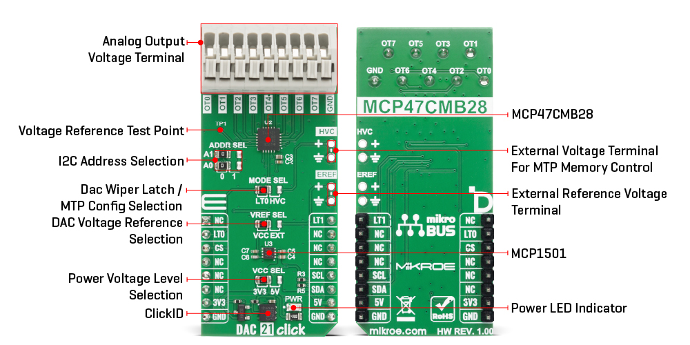
As the reference source for the DAC channels, the board allows selection between several voltage options to accommodate different requirements. The MCP47CMB28 can use an internal reference voltage generated by the onboard MCP1501 precision voltage reference, which provides a stable reference level for the DAC’s operation, or it can operate using its integrated band-gap reference, which typically provides a 1.214V level. In addition to internal reference options, the board also supports the use of an external reference voltage supplied through the EREF terminal, where either buffered or unbuffered signals within the 0 to 5V range may be applied depending on the needs. Selection between internal and external reference sources is handled through the VREF SEL jumper, which can be positioned to either VCC or EXT.
This Click board uses an I2C interface with clock speeds of up to 3.4MHz, ensuring fast communication with the host MCU. The I2C address of the MCP47CMB28 can be easily configured via onboard jumpers marked ADDR SEL, allowing multiple devices to coexist on the same bus. The MCP47CMB28 integrates a Multi-Time Programmable (MTP) memory system that allows each register to be written up to 32 times, providing non-volatile storage for power-up output values, device configuration settings, and general-purpose data locations. To successfully program any MTP location, the device requires a dedicated high-voltage programming signal typically 7.5V with a minimum current capability of 6.4mA, supplied through the HVC terminal on the board.
Access to the MTP memory is enabled by positioning the MODE SEL jumper to the HVC setting, which routes the necessary control signals for high-voltage programming. Alternatively, this jumper can be placed in the LT0 position, enabling control of the DAC Wiper Register Latch 0 via the LT0 pin on the mikroBUS socket. The LT0 pin allows the current values in the volatile DAC0, DAC2, DAC4, and DAC6 registers to be latched out to the corresponding OT0, OT2, OT4, and OT6 analog output terminals, providing precise timing control during multi-channel updates. The board also features an LT1 pin with the same function applied to the complementary channel group, enabling DAC1, DAC3, DAC5, and DAC7 values to be simultaneously transferred to output terminals OT1, OT3, OT5, and OT7.
This Click board™ can operate with either 3.3V or 5V logic voltage levels selected via the VCC SEL jumper. This way, both 3.3V and 5V capable MCUs can use the communication lines properly. Also, this Click board™ comes equipped with a library containing easy-to-use functions and an example code that can be used as a reference for further development.
Type
DAC
Applications
Ideal for sensor calibration, offset and gain trimming, precision reference generation, motor control loops, and a wide range of industrial and consumer control applications
On-board modules
MCP47CMB28 - 12-bit octal voltage output DAC from Microchip
Key Features
12-bit octal buffered voltage output DAC, flexible reference selection, fast 4µs settling time and 1 LSB INL precision, Multi-Time Programmable memory, synchronized multi-channel output latching, I2C communication with configurable address, and more
Interface
I2C
Feature
ClickID
Compatibility
mikroBUS™
Click board size
L (57.15 x 25.4 mm)
Input Voltage
3.3V or 5V
This table shows how the pinout on DAC 21 Click corresponds to the pinout on the mikroBUS™ socket (the latter shown in the two middle columns).
| Notes | Pin | Pin | Notes | ||||
|---|---|---|---|---|---|---|---|
| NC | 1 | AN | PWM | 16 | LT1 | DAC Register Latch 1 | |
| DAC Register Latch 0 | LT0 | 2 | RST | INT | 15 | NC | |
| ID COMM | CS | 3 | CS | RX | 14 | NC | |
| NC | 4 | SCK | TX | 13 | NC | ||
| NC | 5 | MISO | SCL | 12 | SCL | I2C Clock | |
| NC | 6 | MOSI | SDA | 11 | SDA | I2C Data | |
| Power Supply | 3.3V | 7 | 3.3V | 5V | 10 | 5V | Power Supply |
| Ground | GND | 8 | GND | GND | 9 | GND | Ground |
| Label | Name | Default | Description |
|---|---|---|---|
| LD1 | PWR | - | Power LED Indicator |
| JP1 | VCC SEL | Left | Power Voltage Level Selection 3V3/5V: Left position 3V3, Right position 5V |
| JP2 | VREF SEL | Left | DAC Voltage Reference Selection VCC/EXT: Left position 1, Right position 0 |
| JP3-JP4 | ADDR SEL | Left | I2C Address Selection 0/1: Left position 0, Right position 1 |
| JP5 | MODE SEL | Left | DAC Wiper Latch / MTP Config Selection LT0/HVC: Left position LT0, Right position HVC |
| Description | Min | Typ | Max | Unit |
|---|---|---|---|---|
| Supply Voltage | 3.3 | - | 5 | V |
| External Reference Voltage | 0 | - | 5 | V |
| Resolution | - | 12 | - | bit |
| HVC Programming Voltage | - | 7.5 | - | V |
| HVC Programming Current | 6.5 | - | - | mA |
DAC 21 Click demo application is developed using the NECTO Studio, ensuring compatibility with mikroSDK's open-source libraries and tools. Designed for plug-and-play implementation and testing, the demo is fully compatible with all development, starter, and mikromedia boards featuring a mikroBUS™ socket.
Example Description
This example demonstrates the control of DAC output voltage using the DAC 21 Click board. The application sequentially increases the DAC output voltage on all channels in equal steps.
Key Functions
dac21_cfg_setup This function initializes Click configuration structure to initial values.dac21_init This function initializes all necessary pins and peripherals used for this Click board.dac21_set_dac_value This function writes the 12-bit DAC code value to one or more channels and latches the output values by toggling the LAT pins.dac21_set_dac_voltage This function sets the output voltage (in millivolts) for one or more channels by converting it to a corresponding DAC code and updating the device.Application Init
Initializes the driver and performs the Click default configuration.
Application Task
Gradually increases the DAC output voltage on all channels in equal steps every 2 seconds.
Application Output
This Click board can be interfaced and monitored in two ways:
Additional Notes and Information
The complete application code and a ready-to-use project are available through the NECTO Studio Package Manager for direct installation in the NECTO Studio. The application code can also be found on the MIKROE GitHub account.
NOTE: Please be advised that any peripheral devices or accessories shown connected to the Click board™ are not included in the package. Check their availability in our shop or in the YMAN section below.

$889.00

$95.00

$549.00

$299.00

$29.00

$29.00

$6.59

$3.60

$119.00

$299.00

$449.00

$349.00

$349.00

$349.00

$269.00

$249.00

$209.00
