


OFF
GO LOCAL
| Company | Stock | Price |
|---|---|---|


MIKROE-1918
25 g
Status:
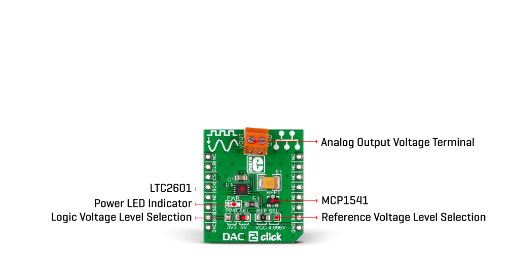
DAC 2 Click is a compact add-on board with a fully-featured digital-to-analog converter. This board features the LTC2601, a highly accurate 16-bit voltage-output digital-to-analog converter from Analog Devices. The LTC2601 has high rail-to-rail output drives and double-buffered data latches, communicating with the target MCU through the compatible SPI interface (write-only). Besides an asynchronous clear pin, which is required in many servo and control applications, this board also has the reference voltage selection, selecting the precision of the converter itself. This Click board™ is suitable for offset and gain control applications, process control and industrial automation, programmable reference, and more.
DAC 2 Click is supported by a mikroSDK compliant library, which includes functions that simplify software development. This Click board™ comes as a fully tested product, ready to be used on a system equipped with the mikroBUS™ socket.
This product is no longer in stock
Availability date:
OFF
| Company | Stock | Price |
|---|---|---|
DAC 2 Click is based on the LTC2601, a single 16-bit rail-to-rail voltage output digital-to-analog converter from Analog Devices with built-in high-performance output buffers. The DAC output (VOUT terminal) can directly drive capacitive loads up to 1000pF or current loads up to 15mA and maintains good linearity to within millivolts of both supply rails. The LTC2601's guaranteed monotonic performance is ideal for digital calibration, trim/adjust, and level setting applications in various applications.
This Click board™ communicates with MCU through a 3-Wire SPI interface (write-only) with a maximum frequency of 50MHz. The LTC2601 also provides an asynchronous clear pin routed to the RST pin of the mikroBUS™ socket, which is required in many servo and control applications. A logic low level at this level-triggered pin clears all registers and causes the DAC voltage outputs to drop to 0V. It also sets all registers to midscale code and causes the DAC voltage outputs to go to midscale.
The MCP3551 uses a reference voltage as the differential voltage range, like any DAC. The reference voltage level selection is performed by positioning the SMD jumper labeled REF SEL to an appropriate position choosing between 3.3V or 5V provided by the mikroBUS™ power rails or 4.096V provided by MCP1541. Those voltages may be used as the reference input that results in accuracy and stability.
This Click board™ can operate with both 3.3V and 5V logic voltage levels selected via the PWR SEL jumper. This way, it is allowed for both 3.3V and 5V capable MCUs to use the communication lines properly. However, the Click board™ comes equipped with a library containing easy-to-use functions and an example code that can be used, as a reference, for further development.
Type
DAC
Applications
Can be used for offset and gain control applications, process control and industrial automation, programmable reference, and more
On-board modules
LTC2601 - digital-to-analog converter from Analog Devices
Key Features
Low power consumption, high performance, reference voltage selection, high precision, flexible dac configuration, SPI compatible interface, and more
Interface
GPIO,SPI
Feature
No ClickID
Compatibility
mikroBUS™
Click board size
S (28.6 x 25.4 mm)
Input Voltage
3.3V or 5V
This table shows how the pinout on DAC 2 Click corresponds to the pinout on the mikroBUS™ socket (the latter shown in the two middle columns).
| Notes | Pin | Pin | Notes | ||||
|---|---|---|---|---|---|---|---|
| NC | 1 | AN | PWM | 16 | NC | ||
| Asynchronous Clear | CLR | 2 | RST | INT | 15 | NC | |
| SPI Chip Select | CS | 3 | CS | RX | 14 | NC | |
| SPI Clock | SCK | 4 | SCK | TX | 13 | NC | |
| SPI Data OUT | SDO | 5 | MISO | SCL | 12 | NC | |
| SPI Data IN | SDI | 6 | MOSI | SDA | 11 | NC | |
| Power Supply | 3.3V | 7 | 3.3V | 5V | 10 | 5V | Power Supply |
| Ground | GND | 8 | GND | GND | 9 | GND | Ground |
| Label | Name | Default | Description |
|---|---|---|---|
| LD1 | PWR | - | Power LED Indicator |
| JP1 | PWR SEL | Right | Logic Level Voltage Selection 3V3/5V: Left position 3V3, Right position 5V |
| JP2 | REF SEL | Left | Reference Voltage Level Selection VCC/4.096V: Left position VCC, Right position 4.096V |
| Description | Min | Typ | Max | Unit |
|---|---|---|---|---|
| Supply Voltage | 3.3 | - | 5 | V |
| Resolution | - | 16 | - | bit |
We provide a library for the DAC 2 Click as well as a demo application (example), developed using Mikroe compilers. The demo can run on all the main Mikroe development boards.
Package can be downloaded/installed directly from NECTO Studio Package Manager(recommended), downloaded from our LibStock™ or found on Mikroe github account.
Library Description
This library contains API for DAC 2 Click driver.
Key functions
This function executes default configuration for LTC2601 click.
This function required percentage value ( from 0% to 100% ) convert to digital input and transforms it to the output voltage from 0 to Vref [mV].
Example Description
This example code presents the usage of DAC 2 Click, and digital-to-analog converter.
 void application_task ( void )
 {
     uint16_t voltage_out;
     uint8_t value_pct;

     for ( value_pct = 0; value_pct <= 100; value_pct += 10 )
     {
         dac2_write_output_voltage_procentage( &dac2, value_pct );
         voltage_out = value_pct * 50;
         log_printf( &logger, "Voltage Output: %d mVrn", voltage_out );

         voltage_out = value_pct;
         log_printf( &logger, "Percentage Output: %d %%rn", voltage_out );

         log_printf( &logger, "--------------------------rn" );
         Delay_ms( 5000 );
     }

     log_printf( &logger, "###############################rn" );
     Delay_ms( 1000 );
 }
The full application code, and ready to use projects can be installed directly from NECTO Studio Package Manager(recommended), downloaded from our LibStock™ or found on Mikroe github account.
Other Mikroe Libraries used in the example:
Additional notes and informations
Depending on the development board you are using, you may need USB UART click, USB UART 2 Click or RS232 Click to connect to your PC, for development systems with no UART to USB interface available on the board. UART terminal is available in all Mikroe compilers.
This Click board™ is supported with mikroSDK - Mikroe Software Development Kit. To ensure proper operation of mikroSDK compliant Click board™ demo applications, mikroSDK should be downloaded from the LibStock and installed for the compiler you are using.
For more information about mikroSDK, visit the official page.
NOTE: Please be advised that any peripheral devices or accessories shown connected to the Click board™ are not included in the package. Check their availability in our shop or in the YMAN section below.

$889.00

$95.00

$549.00

$299.00

$29.00

$29.00

$6.59

$3.60

$119.00

$449.00

$349.00

$349.00

$349.00

$299.00

$269.00

$249.00

$209.00
