


35%
OFF
GO LOCAL
| Company | Stock | Price |
|---|---|---|


MIKROE-1386
30 g
Status:
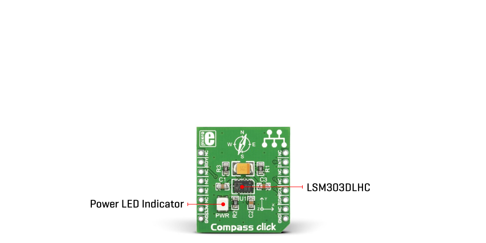
Compass Click is a compact add-on board representing an electronic compass. This board features the LSM303DLHC, an ultra-compact, high-performance e-compass module featuring a 3D digital linear acceleration sensor and a 3D digital magnetic sensor from STMicroelectronics. It includes a specific sensing element capable of measuring both linear acceleration (full-scale of ±2g/±4g/±8g/±16g) and magnetic field (from ±1.3 to ±8.1 gauss full-scale), providing a 16-bit data output through the I2C interface. Readings received from the LSM303DLHC can be processed and used to determine the earth's magnetic north pole. Also, it can be configured to generate interrupt signals by inertial wake-up/free-fall events by the device's position. This Click board™ is suitable for compensated compass, position detection, map rotation, pedometer, display orientation, and many more.
Compass Click is supported by a mikroSDK compliant library, which includes functions that simplify software development. This Click board™ comes as a fully tested product, ready to be used on a system equipped with the mikroBUS™ socket.
NOTE: Compass Click has been moved to the Legacy. As an alternative, we recommend using LSM303AGR Click. For more details on LSM303AGR Click, please visit its product page.
This product is no longer in stock
Availability date:
35%
OFF
| Company | Stock | Price |
|---|---|---|
Compass Click is based on the LSM303DLHC, an ultra-compact, high-performance e-compass module featuring a 3D digital linear acceleration sensor and a 3D digital magnetic sensor from STMicroelectronics. The LSM303DLHC is manufactured using specialized micromachining processes and includes specific sensing elements capable of measuring both the linear acceleration and magnetic field, thus providing a 16-bit data signal to the host MCU through an I2C serial interface. It has linear acceleration full-scales of ±2g/±4g/±8g/±16g and a magnetic field full-scale of ±1.3/±1.9/±2.5/±4.0/±4.7/±5.6/±8.1 gauss, fully selectable by the user.
The LSM303DLHC provides two different acceleration operating modes, respectively reported as “Normal mode” and “Low-power mod”. While normal mode guarantees high resolution, low-power mode further reduces the current consumption. Besides, magnetic and accelerometer parts can be enabled or put into Power-Down mode separately.
Compass Click communicates with MCU using the standard I2C 2-Wire interface to read data and configure settings with a maximum clock frequency of 400kHz. It also features a data-ready signal, routed to the RST pin on the mikroBUS™ socket, which indicates when a new set of measured acceleration and magnetic data are available, simplifying data synchronization in the digital system that uses the device. The LSM303DLHC may also be configured to generate a free-fall interrupt signal according to a programmed acceleration event along the enabled axes.
This Click board™ can be operated only with a 3.3V logic voltage level. The board must perform appropriate logic voltage level conversion before using MCUs with different logic levels. However, the Click board™ comes equipped with a library containing functions and an example code that can be used, as a reference, for further development.
Type
Acceleration,Compass,Magnetic
Applications
Can be used for compensated compass, position detection, map rotation, pedometer, display orientation, and more
On-board modules
LSM303DLHC - e-compass module featuring a 3D digital linear acceleration sensor and a 3D digital magnetic sensor from STMicroelectronics
Key Features
Three magnetic field and acceleration channels, full-scales user-selectable, 16 bit data output, I2C interface, programmable interrupt
generators for free-fall and motion detection, and more
Interface
I2C
Feature
No ClickID
Compatibility
mikroBUS™
Click board size
S (28.6 x 25.4 mm)
Input Voltage
3.3V
Category
Click Boards
This table shows how the pinout on Compass Click corresponds to the pinout on the mikroBUS™ socket (the latter shown in the two middle columns).
| Notes | Pin | Pin | Notes | ||||
|---|---|---|---|---|---|---|---|
| NC | 1 | AN | PWM | 16 | NC | ||
| Data Ready | RDY | 2 | RST | INT | 15 | INT | Interrupt |
| NC | 3 | CS | RX | 14 | NC | ||
| NC | 4 | SCK | TX | 13 | NC | ||
| NC | 5 | MISO | SCL | 12 | SCL | I2C Clock | |
| NC | 6 | MOSI | SDA | 11 | SDA | I2C Data | |
| Power Supply | 3.3V | 7 | 3.3V | 5V | 10 | NC | |
| Ground | GND | 8 | GND | GND | 9 | GND | Ground |
| Label | Name | Default | Description |
|---|---|---|---|
| LD1 | PWR | - | Power LED Indicator |
| Description | Min | Typ | Max | Unit |
|---|---|---|---|---|
| Supply Voltage | - | 3.3 | - | V |
| Acceleration Measurement Range | ±2 | - | ±16 | g |
| Magnetic Measurement Range | ±1.3 | - | ±8.1 | gauss |
| Resolution | - | 16 | - | bit |
| Operating Temperature Range | -40 | +25 | +85 | °C |
We provide a library for the Compass Click as well as a demo application (example), developed using MikroElektronika compilers. The demo can run on all the main MikroElektronika development boards.
Package can be downloaded/installed directly from NECTO Studio Package Manager(recommended way), downloaded from our LibStock™ or found on Mikroe github account.
Library Description
This library contains API for Compass Click driver.
Key functions
This function reads data for megnetic axes.
This function reads data for accelerometer axes.
This function writes magnet data to the desired register.
Example Description
This application measures magnetic and accelerometer axes data and shows them over USBUART
void application_task ( void )
 {
     int16_t accel_axis[ 3 ];
     int16_t magnet_axis[ 3 ];

     compass_read_magnet_axis( &compass, &magnet_axis[ 0 ], &magnet_axis[ 1 ], &magnet_axis[ 2 ] );
     log_printf( &logger, "Magnet axis -- X: %d Y: %d  Z: %d rn", magnet_axis[ 0 ], magnet_axis[ 1 ], magnet_axis[ 2 ] );

     compass_read_accel_axis ( &compass, &accel_axis[ 0 ], &accel_axis[ 1 ], &accel_axis[ 2 ] );
     log_printf( &logger, "Magnet axis -- X: %d Y: %d  Z: %d rn", accel_axis[ 0 ], accel_axis[ 1 ], accel_axis[ 2 ] );

     log_printf( &logger, " rn");
     Delay_ms( 1000 );
 }
The full application code, and ready to use projects can be installed directly from NECTO Studio Package Manager(recommended way), downloaded from our LibStock™ or found on Mikroe github account.
Other Mikroe Libraries used in the example:
Additional notes and informations
Depending on the development board you are using, you may need USB UART click, USB UART 2 Click or RS232 Click to connect to your PC, for development systems with no UART to USB interface available on the board. UART terminal is available in all MikroElektronika compilers.
This Click board™ is supported with mikroSDK - MikroElektronika Software Development Kit. To ensure proper operation of mikroSDK compliant Click board™ demo applications, mikroSDK should be downloaded from the LibStock and installed for the compiler you are using.
For more information about mikroSDK, visit the official page.
NOTE: Please be advised that any peripheral devices or accessories shown connected to the Click board™ are not included in the package. Check their availability in our shop or in the YMAN section below.

$889.00

$95.00

$549.00

$299.00

$29.00

$29.00

$6.59

$3.60

$119.00

$449.00

$349.00

$349.00

$349.00

$299.00

$269.00

$249.00

$209.00
