


OFF
GO LOCAL
| Company | Stock | Price |
|---|---|---|


MIKROE-6713
20 g
Status:
Charger 31 Click is a compact add-on board designed to provide intelligent charging for single-cell Li-ion or Li-polymer batteries in embedded applications. It is based on the MP2724, a single-cell buck charger with USB Type-C sink mode from Monolithic Power Systems (MPS), which delivers a low-impedance power path to optimize charging efficiency, reduce charging time, and extend battery life. It features a narrow-voltage DC (NVDC) power management structure, configurable charge currents from 40mA to 2.2A via I2C, and a fully customizable JEITA profile with an additional NTC thermistor input for enhanced safety. Besides, there is also Power-Good and Charge Status LED indicators, a Battery MOSFET Reset button (MRST) for hardware power-on reset, Click Snap format, and a SYS terminal providing a regulated system output. Charger 31 Click is ideal for ≤15W USB-powered devices, Bluetooth headphones and speakers, point-of-sale terminals, and portable cameras.
Charger 31 Click is fully compatible with the mikroBUS™ socket and can be used on any host system supporting the mikroBUS™ standard. It comes with the mikroSDK open-source libraries, offering unparalleled flexibility for evaluation and customization. What sets this Click board™ apart is the groundbreaking ClickID feature, enabling your host system to automatically detect and identify this add-on board, alongside a Click Snap feature introducing a new level of flexibility and ease of use.
This product is no longer in stock
Availability date:
OFF
| Company | Stock | Price |
|---|---|---|
Charger 31 Click is based on the MP2724, a single-cell buck charger with USB Type-C sink mode from Monolithic Power Systems (MPS) designed to provide intelligent charging for single-cell Li-ion or Li-polymer batteries. This highly integrated 2.2A switch-mode battery management device features a narrow-voltage DC (NVDC) power management structure that delivers a low-impedance power path to optimize charging efficiency, reduce battery charging time, and extend battery life during discharging. It supports USB Type-C sink mode to detect the current capability of a connected USB Type-C adapter and offers an I2C interface for complete operating control, allowing users to configure charging parameters and monitor status and interrupts. With its configurable parameters, multiple safety features, and versatile system integration options, Charger 31 Click is an ideal solution for applications such as ≤15W USB-powered devices, Bluetooth headphones and speakers, point-of-sale terminals, and portable cameras that require single-cell battery charging and management.
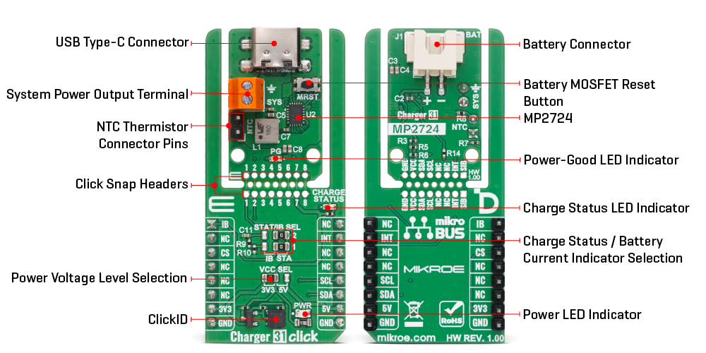
The MP2724 also supports a fully customizable JEITA profile with configurable temperature windows and actions, and an additional Negative Temperature Coefficient thermistor input (NTC header) for enhanced safety. It allows configurable charge currents from 40mA to 2.2A via the I2C interface and integrates a Power-Good red LED indicator and a Charge Status red LED indicator to provide clear visual feedback. The board features a Battery MOSFET Reset button (MRST) that enables a hardware power-on reset by toggling the internal FET status when the input source is absent, ensuring the system powered by the battery can be reset easily. The SYS terminal provides system power output from 3.7V to 3.94V, with a typical value of 3.82V, making it ideal for powering external circuits.
This Click board™ is designed in a unique format supporting the newly introduced MIKROE feature called "Click Snap." Unlike the standardized version of Click boards, this feature allows the main sensor/IC/module area to become movable by breaking the PCB, opening many new possibilities for implementation. Thanks to the Snap feature, the MP2724 can operate autonomously by accessing its signals directly on the pins marked 1-8. Additionally, the Snap part includes a specified and fixed screw hole position, enabling users to secure the Snap board in their desired location.
Alongside the I2C communication pins, the board uses an INT pin for additional interrupt signaling and includes a set of jumpers labeled STAT/IB SEL for charge status or battery current indication selection. When both jumpers are in the STAT position, the board activates the charge status indication function, where the CHARGE STATUS LED glows red during charging and blinks when charging is suspended due to conditions such as battery overvoltage, input overvoltage, timer faults, or NTC faults. When the jumpers are in the IB position, the IB pin outputs a signal proportional to the battery’s charge or discharge current, enabling precise current monitoring.
This Click board™ can operate with either 3.3V or 5V logic voltage levels selected via the VCC SEL jumper. This way, both 3.3V and 5V capable MCUs can use the communication lines properly. Also, this Click board™ comes equipped with a library containing easy-to-use functions and an example code that can be used as a reference for further development.
Click Snap is an innovative feature of our standardized Click add-on boards, designed to bring greater flexibility and optimize your prototypes. By simply snapping the PCB along predefined lines, you can easily detach the main sensor/IC/module area, reducing the overall size, weight, and power consumption - ideal for the final phase of prototyping. For more details about Click Snap, visit the official page dedicated to this feature.
Type
Battery charger
Applications
Ideal for ≤15W USB-powered devices, Bluetooth headphones and speakers, point-of-sale terminals, and portable cameras
On-board modules
MP2724 - single-cell buck-charger with USB type-C sink mode and 15mA termination current from MPS
Key Features
Narrow-voltage DC (NVDC) power management structure, configurable charge currents, a fully customizable JEITA profile with additional NTC thermistor input, USB Type-C sink mode for adapter current capability detection, Power-Good and Charge Status LED indicators, a Battery MOSFET Reset button, a SYS terminal providing regulated system output, Click Snap format, and more
Interface
I2C
Feature
Click Snap,ClickID
Compatibility
mikroBUS™
Click board size
L (57.15 x 25.4 mm)
Input Voltage
3.3V or 5V,External
This table shows how the pinout on Charger 31 Click corresponds to the pinout on the mikroBUS™ socket (the latter shown in the two middle columns).
| Notes | Pin | Pin | Notes | ||||
|---|---|---|---|---|---|---|---|
| Battery Current Monitor | IB | 1 | AN | PWM | 16 | NC | |
| NC | 2 | RST | INT | 15 | INT | Interrupt | |
| ID COMM | CS | 3 | CS | RX | 14 | NC | |
| NC | 4 | SCK | TX | 13 | NC | ||
| NC | 5 | MISO | SCL | 12 | SCL | I2C Clock | |
| NC | 6 | MOSI | SDA | 11 | SDA | I2C Data | |
| Power Supply | 3.3V | 7 | 3.3V | 5V | 10 | 5V | Power Supply |
| Ground | GND | 8 | GND | GND | 9 | GND | Ground |
| Label | Name | Default | Description |
|---|---|---|---|
| LD1 | PWR | - | Power LED Indicator |
| LD2 | PG | - | Power-Good LED Indicator |
| LD3 | CHARGE STATUS | - | Charge Status LED Indicator |
| JP1 | VCC SEL | Left | Power Voltage Level Selection 3V3/5V: Left position 3V3, Right position 5V |
| T1 | MRST | - | Battery MOSFET Reset Button |
| Description | Min | Typ | Max | Unit |
|---|---|---|---|---|
| Supply Voltage | 3.3 | - | 5 | V |
| USB Input Voltage | - | 5 | - | V |
| System Output Voltage (SYS) | 3.7 | - | 3.94 | V |
| Charge Current | 0.04 | - | 2.2 | A |
Charger 31 Click demo application is developed using the NECTO Studio, ensuring compatibility with mikroSDK's open-source libraries and tools. Designed for plug-and-play implementation and testing, the demo is fully compatible with all development, starter, and mikromedia boards featuring a mikroBUS™ socket.
Example Description
This example demonstrates the operation of the Charger 31 Click board by monitoring the status registers and displaying information related to power input, charging state, battery presence, and possible faults.
Key Functions
charger31_cfg_setup This function initializes Click configuration structure to initial values.charger31_init This function initializes all necessary pins and peripherals used for this Click board.charger31_default_cfg This function executes a default configuration of Charger 31 Click board.charger31_read_status This function reads multiple status registers and stores the values into the provided status structure.Application Init
Initializes the logger and the Click board, then performs the default configuration.
Application Task
Periodically reads the status registers and logs messages for VIN readiness, battery presence, charging status, and charging faults.
Application Output
This Click board can be interfaced and monitored in two ways:
Additional Notes and Information
The complete application code and a ready-to-use project are available through the NECTO Studio Package Manager for direct installation in the NECTO Studio. The application code can also be found on the MIKROE GitHub account.
NOTE: Please be advised that any peripheral devices or accessories shown connected to the Click board™ are not included in the package. Check their availability in our shop or in the YMAN section below.

$15.00

$1.20

$1.74

$3.00

$1.20

$10.80

$889.00

$95.00

$549.00

$299.00

$29.00

$29.00

$6.59

$3.60

$119.00

$449.00

$349.00

$349.00

$349.00

$299.00

$269.00

$249.00

$209.00
