


OFF
GO LOCAL
| Company | Stock | Price |
|---|---|---|


MIKROE-6652
17 g
Status:
Charger 29 Click is a compact add-on board designed for single-cell battery charging and power path management in low-power, portable applications. It is based on the BQ25188 linear battery charger IC from Texas Instruments. This Click board™ supports fast charge currents from 5mA to 1A and system loads up to 3A, with ultra-low quiescent current to extend battery life. It features a wide input voltage range (3V–18V via VEXT or 5V via mikroBUS™), and provides a regulated system output adjustable between 4.4V and 5.5V. The integrated battery temperature monitoring supports configurable NTC thresholds and JEITA compliance. With built-in protections including overvoltage, overcurrent, thermal regulation, and battery fault detection, Charger 29 Click offers a flexible and safe power solution. It is ideal for smart wearables, TWS headsets, AR/VR devices, and other portable or battery-powered systems.
Charger 29 Click is fully compatible with the mikroBUS™ socket and can be used on any host system supporting the mikroBUS™ standard. It comes with the mikroSDK open-source libraries, offering unparalleled flexibility for evaluation and customization. What sets this Click board™ apart is the groundbreaking ClickID feature, enabling your host system to automatically detect and identify this add-on board, alongside a Click Snap feature introducing a new level of flexibility and ease of use.
This product is no longer in stock
Availability date:
OFF
| Company | Stock | Price |
|---|---|---|
Charger 29 Click is based on the BQ25188, a highly integrated linear battery charger from Texas Instruments, optimized for extending battery life through its ultra-low quiescent current operation. This board is made for single-cell battery charging and power path management in low-power, space-constrained applications. It supports fast charging currents configurable from 5mA to 1A, making it suitable for various battery chemistries including Li-ion, Li-Polymer, and LiFePO4. The board allows a system load of up to 3A, thanks to the 55mΩ ON-resistance battery FET and advanced power path control, ensuring easy supply switching between input and battery sources.
Charger 29 Click is capable of operating from a wide input voltage range of 3V to 18V via the VEXT header, allowing battery-to-battery charging scenarios, while also supporting 5V input from the mikroBUS™ power rail. Input power source selection is easily managed using the VIN SEL jumper. The charger provides a regulated system output on the SYS header, adjustable from 4.4V to 5.5V, and also supports battery voltage tracking. The BQ25188 integrates intelligent battery temperature monitoring via the TS pin with configurable NTC thresholds, including full JEITA compliance, to ensure safe charging in wearable and portable devices.
Moreover, the board includes comprehensive protection mechanisms such as input overvoltage, battery short and overcurrent protection, thermal regulation and shutdown, and battery thermal fault detection. Its battery regulation voltage can be finely tuned with 0.5% accuracy in 10mV steps across a 3.6V to 4.65V range. Charger 29 Click is a highly adaptable and reliable power management solution, ideal for use in smart wearables, TWS headsets and charging cases, AR/VR glasses, retail automation systems, and building automation applications.
This Click board™ is designed in a unique format supporting the newly introduced MIKROE feature called "Click Snap." Unlike the standardized version of Click boards, this feature allows the main sensor/IC/module area to become movable by breaking the PCB, opening up many new possibilities for implementation. Thanks to the Snap feature, the BQ25188 can operate autonomously by accessing its signals directly on the pins marked 1-8. Additionally, the Snap part includes a specified and fixed screw hole position, enabling users to secure the Snap board in their desired location.
This Click board™ uses an I2C interface with clock speeds of up to 400kHz, ensuring fast communication with the host MCU. Beyond communication pins, this board is also equipped with an interrupt (INT) pin that signals fault interrupts, and a MR button to send interrupts to the host MCU as a button is pressed or to allow the application end user to reset the system.
This Click board™ can operate with either 3.3V or 5V logic voltage levels selected via the VIO SEL jumper. This way, both 3.3V and 5V capable MCUs can use the communication lines properly. Also, this Click board™ comes equipped with a library containing easy-to-use functions and an example code that can be used as a reference for further development.
Click Snap is an innovative feature of our standardized Click add-on boards, designed to bring greater flexibility and optimize your prototypes. By simply snapping the PCB along predefined lines, you can easily detach the main sensor/IC/module area, reducing the overall size, weight, and power consumption - ideal for the final phase of prototyping. For more details about Click Snap, visit the official page dedicated to this feature.
Type
Battery charger
Applications
Ideal for smart wearables, TWS headsets, AR/VR devices, and other portable or battery-powered systems
On-board modules
BQ25188 - 1-cell linear battery charger with power path from Texas Instruments
Key Features
Support for fast charging currents from 5mA to 1A, system load capability up to 3A, ultra-low quiescent current operation, wide input voltage range, adjustable regulated system output, configurable battery regulation voltage in 10mV steps with 0.5% accuracy, support for Li-ion, Li-Polymer, and LiFePO4 chemistries, advanced power path management, integrated battery temperature monitoring with configurable NTC thresholds and JEITA compliance, multiple safety protections, Click Snap, and more
Interface
I2C
Feature
Click Snap,ClickID
Compatibility
mikroBUS™
Click board size
M (42.9 x 25.4 mm)
Input Voltage
3.3V or 5V,External
This table shows how the pinout on Charger 29 Click corresponds to the pinout on the mikroBUS™ socket (the latter shown in the two middle columns).
| Notes | Pin | Pin | Notes | ||||
|---|---|---|---|---|---|---|---|
| NC | 1 | AN | PWM | 16 | NC | ||
| NC | 2 | RST | INT | 15 | INT | Interrupt | |
| ID COMM | CS | 3 | CS | RX | 14 | NC | |
| NC | 4 | SCK | TX | 13 | NC | ||
| NC | 5 | MISO | SCL | 12 | SCL | I2C Clock | |
| NC | 6 | MOSI | SDA | 11 | SDA | I2C Data | |
| Power Supply | 3.3V | 7 | 3.3V | 5V | 10 | 5V | Power Supply |
| Ground | GND | 8 | GND | GND | 9 | GND | Ground |
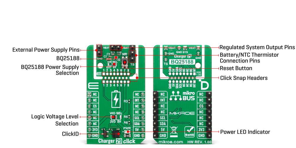
| Label | Name | Default | Description |
|---|---|---|---|
| LD1 | PWR | - | Power LED Indicator |
| JP1 | VIO SEL | Left | Logic Voltage Level Selection 3V3/5V: Left position 3V3, Right position 5V |
| JP2 | VIN SEL | Left | BQ25188 Power Supply Selection EXT/5V: Left position EXT, Right position 5V |
| T1 | MR | - | Reset Button |
| Description | Min | Typ | Max | Unit |
|---|---|---|---|---|
| Supply Voltage | 3.3 | - | 5 | V |
| External Supply Voltage | 3 | - | 18 | V |
| Charge Current | - | - | 1 | A |
| System Load Current | - | - | 3 | A |
| Battery Regulation Voltage | 3.6 | - | 4.65 | V |
| System Output Voltage | 4.4 | - | 5.5 | V |
Charger 29 Click demo application is developed using the NECTO Studio, ensuring compatibility with mikroSDK's open-source libraries and tools. Designed for plug-and-play implementation and testing, the demo is fully compatible with all development, starter, and mikromedia boards featuring a mikroBUS™ socket.
Example Description
This example demonstrates the use of the Charger 29 Click board. The application initializes the device and periodically checks the charging status. The status is displayed over the UART terminal and reflects whether the battery is charging in constant current (CC) mode, constant voltage (CV) mode, fully charged, or not charging.
Key Functions
charger29_cfg_setup This function initializes Click configuration structure to initial values.charger29_init This function initializes all necessary pins and peripherals used for this Click board.charger29_default_cfg This function executes a default configuration of Charger 29 Click board.charger29_enable_charging This function enables charging by clearing the charging disable bit.charger29_set_charging_current This function sets the charging current based on the specified value in milliamps.charger29_read_status This function reads the status and flag registers of the Charger 29 Click board.Application Init
Initializes the logger and the Charger 29 Click driver and applies default configuration.
Application Task
Periodically reads and logs the charging status once per second.
Application Output
This Click board can be interfaced and monitored in two ways:
Additional Notes and Information
The complete application code and a ready-to-use project are available through the NECTO Studio Package Manager for direct installation in the NECTO Studio. The application code can also be found on the MIKROE GitHub account.
NOTE: Please be advised that any peripheral devices or accessories shown connected to the Click board™ are not included in the package. Check their availability in our shop or in the YMAN section below.

$15.00

$1.20

$1.74

$3.00

$1.20

$95.00

$889.00

$549.00

$299.00

$29.00

$29.00

$3.30

$3.60

$119.00

$449.00

$349.00

$349.00

$349.00

$299.00

$269.00

$249.00

$209.00
