


20%
OFF
GO LOCAL
| Company | Stock | Price |
|---|---|---|


MIKROE-6645
23 g
Status:
Cap Slider 3 Click is a compact add-on board that provides a reliable capacitive sliding interface for touch-based control applications, ideal for implementing gesture-based user input in embedded systems. It is based on the IQS323, a highly flexible ProxFusion® sensor fusion IC from Azoteq, optimized for detecting slide gestures in both UP and DOWN directions. The IQS323 supports on-chip processing, automatic tuning, noise filtering, debounce and hysteresis, dual-direction trigger detection, and ultra-low power operation including a Halt and distributed ULP mode. Communication is handled via the standard I2C interface with a configurable RDY pin for efficient event handling, while two onboard LEDs indicate touch activity and power status. Cap Slider 3 Click is most suitable for wearable electronics, waterproof or sealed interfaces, SAR safety mechanisms, and low-power proximity or wake-up applications.
Cap Slider 3 Click is fully compatible with the mikroBUS™ socket and can be used on any host system supporting the mikroBUS™ standard. It comes with the mikroSDK open-source libraries, offering unparalleled flexibility for evaluation and customization. What sets this Click board™ apart is the groundbreaking ClickID feature, enabling your host system to automatically detect and identify this add-on board.
This product is no longer in stock
Availability date:
20%
OFF
| Company | Stock | Price |
|---|---|---|
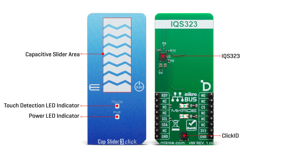
Cap Slider 3 Click is based on the IQS323, a highly flexible ProxFusion® sensor fusion IC from Azoteq, designed to provide a reliable capacitive sliding interface for various touch-based control applications. The front side of the board incorporates a single large sensor pad that allows for intuitive sliding gestures, providing a smooth user experience. The IQS323 communicates over the standard I2C interface and performs all processing on-chip, allowing it to function effectively even in ultra-low-power modes. The built-in feature set includes automatic tuning for optimal sensitivity under varying environmental conditions, advanced noise filtering for stable readings, and differential measurement support via reference channels to improve accuracy.
The IQS323 also integrates debounce and hysteresis mechanisms to prevent false triggers, as well as dual-direction trigger indication for clear response to sliding gestures in both directions. Additionally, the IQS323 supports a Halt Mode that significantly reduces power consumption, along with a distributed ultra-low-power (ULP) mode that intelligently balances response time and energy efficiency. These features make Cap Slider 3 Click an ideal solution for applications that require robust, low-power touch or proximity interfaces such as wearable electronics like fitness bands and smartwatches, presence or wear detection mechanisms, SAR (Specific Absorption Rate) safety sensors, and wake-up buttons in battery-powered systems.
As mentioned earlier, this Click contains a 3-segment capacitive sensing slider that can detect a slide in either the UP or DOWN direction, as well as two LED indicators (TOUCH and PWR). These are the only elements on the top side of the board, allowing the protective acrylic plexiglass layer placement. If a touch event is detected on slider area, the state of the TOUCH LED will be changed, indicating an activated channel; more precisely, touch has been detected on that specific field.
Cap Slider 3 Click communicates with MCU using the standard I2C 2-Wire interface with a maximum clock frequency of 1MHz, fully adjustable through software registers. An additional ready signal, routed on the RDY pin of the mikroBUS™ socket, is added, which indicates when the communication window is available with new data for optimal response. Thus, it is optimal for the response rate to use the INT pin as a communication trigger.
This Click board™ can be operated only with a 3.3V logic voltage level. The board must perform appropriate logic voltage level conversion before using MCUs with different logic levels. It also comes equipped with a library containing functions and example code that can be used as a reference for further development.
Type
Capacitive
Applications
Ideal for wearable electronics, waterproof or sealed interfaces, SAR safety mechanisms, and low-power proximity or wake-up applications
On-board modules
IQS323 - ProxFusion® sensor fusion IC from Azoteq
Key Features
3-segment capacitive sensing slider, on-chip automatic tuning, advanced noise filtering, differential measurement using reference channels, debounce and hysteresis functionality, dual-direction trigger detection, ultra-low-power distributed mode, Halt Mode for reduced consumption, I2C communication interface, RDY pin for data-ready signaling, and more
Interface
I2C
Feature
ClickID
Compatibility
mikroBUS™
Click board size
L (57.15 x 25.4 mm)
Input Voltage
3.3V
This table shows how the pinout on Cap Slider 3 Click corresponds to the pinout on the mikroBUS™ socket (the latter shown in the two middle columns).
| Notes | Pin | Pin | Notes | ||||
|---|---|---|---|---|---|---|---|
| NC | 1 | AN | PWM | 16 | RDY | Data Ready Indicator | |
| NC | 2 | RST | INT | 15 | NC | ||
| ID COMM | CS | 3 | CS | RX | 14 | NC | |
| NC | 4 | SCK | TX | 13 | NC | ||
| NC | 5 | MISO | SCL | 12 | SCL | I2C Clock | |
| NC | 6 | MOSI | SDA | 11 | SDA | I2C Data | |
| Power Supply | 3.3V | 7 | 3.3V | 5V | 10 | NC | |
| Ground | GND | 8 | GND | GND | 9 | GND | Ground |
| Label | Name | Default | Description |
|---|---|---|---|
| LD1 | PWR | - | Power LED Indicator |
| LD2 | TOUCH | - | Touch Detection LED Indicator |
| Description | Min | Typ | Max | Unit |
|---|---|---|---|---|
| Supply Voltage | - | 3.3 | - | V |
| Slider Type | 3-Segment Capacitive | |||
Cap Slider 3 Click demo application is developed using the NECTO Studio, ensuring compatibility with mikroSDK's open-source libraries and tools. Designed for plug-and-play implementation and testing, the demo is fully compatible with all development, starter, and mikromedia boards featuring a mikroBUS™ socket.
Example Description
This example demonstrates the use of the Cap Slider 3 Click board by initializing the device and reading the current slider position. The application logs the detected slider position in real-time.
Key Functions
capslider3_cfg_setup This function initializes Click configuration structure to initial values.capslider3_init This function initializes all necessary pins and peripherals used for this Click board.capslider3_default_cfg This function executes a default configuration of Cap Slider 3 Click board.capslider3_read_data This function reads various system information and sensor data from the Click board.Application Init
Initializes the logger and the Cap Slider 3 Click driver.
Application Task
Continuously reads and logs the slider position detected by the Cap Slider 3 Click board.
Application Output
This Click board can be interfaced and monitored in two ways:
Additional Notes and Information
The complete application code and a ready-to-use project are available through the NECTO Studio Package Manager for direct installation in the NECTO Studio. The application code can also be found on the MIKROE GitHub account.
NOTE: Please be advised that any peripheral devices or accessories shown connected to the Click board™ are not included in the package. Check their availability in our shop or in the YMAN section below.

$533.40

$66.50

$329.40

$239.20

$29.00

$23.20

$3.30

$2.88

$95.20

$314.30

$244.30

$244.30

$191.95

$209.30

$215.20

$199.20

$167.20
