


OFF
GO LOCAL
| Company | Stock | Price |
|---|---|---|


MIKROE-6348
22 g
Status:
Brushless 31 Click is a compact add-on board for precise and efficient brushless motor control. This board features the TB6605FTG, a three-phase full sine-wave brushless motor controller from Toshiba Semiconductor. The board features six onboard external N-channel MOSFETs for smooth motor operation, sine-wave PWM driving with 2-phase modulation for high efficiency and low noise, and includes essential functions like dead time, brake, and manual/auto lead-angle control. It supports clockwise and counterclockwise rotation and offers motor lock protection for added safety. Brushless 31 Click is ideal for home appliances, fans, and office equipment applications, where reliable and precise motor control is critical.
Brushless 31 Click is fully compatible with the mikroBUS™ socket and can be used on any host system supporting the mikroBUS™ standard. It comes with the mikroSDK open-source libraries, offering unparalleled flexibility for evaluation and customization. What sets this Click board™ apart is the groundbreaking ClickID feature, enabling your host system to seamlessly and automatically detect and identify this add-on board.
This product is no longer in stock
Availability date:
OFF
| Company | Stock | Price |
|---|---|---|
Brushless 31 Click is based on the TB6605FTG, a three-phase full sine-wave brushless motor controller from Toshiba Semiconductor, specifically made for home appliances, fans, and office equipment applications. This Click board™ uses the advanced capabilities of the TB6605FTG to control brushless motors through six onboard external N-channel MOSFETs (SSM6K513NU), ensuring smooth and efficient operation. The TB6605FTG features sine-wave PWM driving with 2-phase modulation, which enables high efficiency and low noise performance. Additionally, it includes a dead time function, brake, and start mechanisms to enhance motor control precision. The speed command is managed via a PWM input, and the auto lead-angle control function, which is disabled by default, can be manually activated to automatically adjust the lead angle based on motor speed, ensuring optimal performance once enabled. Furthermore, the board supports both clockwise and counterclockwise rotation (DIR pin) and is equipped with a motor lock protection function for added safety during operation.
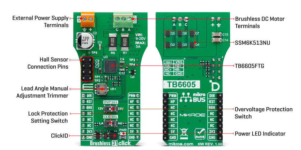
This Click board™ is designed to support a wide range of external power supplies, accepting input voltages from 9V to 28V through terminals on the board's front side marked VIN. It can deliver a maximum output current of up to 5A, providing robust power for driving BLDC motors connected to the OUT terminals. The board also includes dedicated pins for additional Hall sensor connections via the J1 header to enhance the motor's performance and precision further. The VR1 trimmer, allows manual adjustment of the Lead Angle (auto Lead Angle function is disabled by default) to ensure e optimal motor performance. Various BLDC motors, particularly those with built-in Hall sensors, such as the BLDC Motor with Hall Sensor available from MIKROE, making it a versatile solution for high-precision motor control applications.
In addition to the PWM pin for motor speed control and the DIR pin for controlling rotational direction, this Click board™ uses several control pins from the mikroBUS™ socket. The RST pin serves the START function, initiating motor operation when set to a LOW logic state and stopping it when set to HIGH. The BRK pin is dedicated to motor brake control, providing precise braking functionality. Additionally, the HP pin outputs the signal from the Hall pulse monitor, offering real-time feedback on the motor's position and speed.
The onboard switches serve crucial functions for motor control. The OVP SEL switch allows you to toggle the output drive mode based on the power supply voltage, either 12V or 24V. This is particularly important when the motor's rotation speed decreases rapidly due to a drop in PWM duty in the 180° energization mode (sine-wave drive). In such cases, the power supply voltage can rise as current flows back from the motor to the power source. The OVP SEL function is designed to suppress this voltage boost by switching the operation from 180° energization (synchronous rectification) to 120° energization when the supply voltage increases. The CLD SEL switch provides control over the motor lock protection feature of the TB6605FTG, which turns OFF the output power FETs when the motor is locked. This switch allows you to choose between Auto (AU) and Latch (LA) modes during a motor lock condition. In the Auto recovery mode, the operation recovers with three times the lock detecting time.
This Click board™ can operate with either 3.3V or 5V logic voltage levels. This way, both 3.3V and 5V capable MCUs can use the communication lines properly. Also, this Click board™ comes equipped with a library containing easy-to-use functions and an example code that can be used as a reference for further development.
Type
Brushless
Applications
Ideal for home appliances, fans, and office equipment
On-board modules
TB6605FTG - three-phase full sine-wave brushless motor controller from Toshiba Semiconductor
Key Features
Sine-wave PWM driving with 2-phase modulation, broad range of external power supply, maximum output current of up to 5A, Hall sensor connections, dead time, brake, start, and auto lead-angle control, motor lock protection, and more
Interface
GPIO,PWM
Feature
ClickID
Compatibility
mikroBUS™
Click board size
L (57.15 x 25.4 mm)
Input Voltage
3.3V,5V,External
This table shows how the pinout on Brushless 31 Click corresponds to the pinout on the mikroBUS™ socket (the latter shown in the two middle columns).
| Notes | Pin | Pin | Notes | ||||
|---|---|---|---|---|---|---|---|
| Direction Control | DIR | 1 | AN | PWM | 16 | PWM | PWM Input |
| Start-Stop / ID SEL | RST | 2 | RST | INT | 15 | HP | Hall Pulse Monitor |
| Brake / ID COMM | BRK | 3 | CS | RX | 14 | NC | |
| NC | 4 | SCK | TX | 13 | NC | ||
| NC | 5 | MISO | SCL | 12 | NC | ||
| NC | 6 | MOSI | SDA | 11 | NC | ||
| Power Supply | 3.3V | 7 | 3.3V | 5V | 10 | 5V | Power Supply |
| Ground | GND | 8 | GND | GND | 9 | GND | Ground |
| Label | Name | Default | Description |
|---|---|---|---|
| LD1 | PWR | - | Power LED Indicator |
| SW1 | CLD SEL | Left | Lock Protection Mode Switch LA/AU: Left position LA, Right position AU |
| SW2 | OVP SEL | Left | Overvoltage Level Protection Switch 12V/24V: Left position 12V, Right position 24V |
| VR1 | VR1 | - | Lead Angle Manual Adjustment Trimmer |
| Description | Min | Typ | Max | Unit |
|---|---|---|---|---|
| Supply Voltage | 3.3 | - | 5 | V |
| External Power Supply | 9 | - | 28 | V |
| Output Current | - | - | 5 | A |
We provide a library for the Brushless 31 Click as well as a demo application (example), developed using MIKROE compilers. The demo can run on all the main MIKROE development boards.
Package can be downloaded/installed directly from NECTO Studio Package Manager (recommended), downloaded from our LibStock™ or found on MIKROE github account.
Library Description
This library contains API for Brushless 31 Click driver.
Key functions
brushless31_set_duty_cycle This function sets the PWM duty cycle in percentages ( Range[ 0..1 ] ).
brushless31_pull_brake This function pulls brake by setting the BRAKE pin to low logic state.
brushless31_switch_direction This function switches the direction of motor rotation by toggling the DIR pin logic state.
Example Description
This example demonstrates the use of the Brushless 31 Click by driving the motor in both directions at different speeds.
void application_task ( void )
 {
     static int8_t duty_cnt = 8;
     static int8_t duty_inc = -1;
     float duty = duty_cnt / 10.0;

     brushless31_set_duty_cycle ( &brushless31, duty );
     log_printf( &logger, "> Duty: %d%%rn", ( uint16_t )( duty_cnt * 10 ) );

     Delay_ms ( 500 );

     duty_cnt += duty_inc;
     if ( duty_cnt > 8 )
     {
         duty_cnt = 8;
         duty_inc = -1;
         log_printf( &logger, " Pull brakern" );
         brushless31_pull_brake ( &brushless31 );
         Delay_ms ( 1000 );
         log_printf( &logger, " Switch directionrn" );
         brushless31_switch_direction ( &brushless31 );
         Delay_ms ( 1000 );
         log_printf( &logger, " Release brakern" );
         brushless31_release_brake ( &brushless31 );
         Delay_ms ( 1000 );
     }
     else if ( duty_cnt < 0 )
     {
         duty_cnt = 1;
         duty_inc = 1;
     }
 }
The full application code, and ready to use projects can be installed directly from NECTO Studio Package Manager (recommended), downloaded from our LibStock™ or found on MIKROE github account.
Other MIKROE Libraries used in the example:
Additional notes and informations
Depending on the development board you are using, you may need USB UART click, USB UART 2 Click or RS232 Click to connect to your PC, for development systems with no UART to USB interface available on the board. UART terminal is available in all MIKROE compilers.
This Click board™ is supported with mikroSDK - MIKROE Software Development Kit. To ensure proper operation of mikroSDK compliant Click board™ demo applications, mikroSDK should be downloaded from the LibStock and installed for the compiler you are using.
For more information about mikroSDK, visit the official page.
NOTE: Please be advised that any peripheral devices or accessories shown connected to the Click board™ are not included in the package. Check their availability in our shop or in the YMAN section below.

$78.00

$889.00

$95.00

$549.00

$299.00

$29.00

$29.00

$3.30

$3.60

$119.00

$449.00

$349.00

$349.00

$349.00

$299.00

$269.00

$249.00

$209.00
