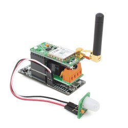
If you are a beginner this is probably the best starting point for you. It is always nice and interesting to make something useful.
The project works with a motion sensor which reports its' own state through a simple GPIO pin. Then we have the Relay click board which can also be controlled with simple GPIO pins and used to start the alarm and turn on the lights, for example. Finally, there is a GSM click board used to report the motion event. GSM uses UART for the communication so handling of the UART will be the most complex thing in this project.
Example
The easiest way to start the project is to draw your idea using an algorithm. Draw very basically without going into the details. So your algorithm might looks like this one.

As you can see everything except the initialization should be inside the loop. Initialization is what we need to do before entering the loop. We have to initialize all pins needed, UART for communication with the GSM click board and variables that will be used to check the state of the application. Let's focus on the conditions now. We have 4 of them :
- Alarm active
- Motion detected
- Button A press
- Button B press
Motion detected condition is actually the state of the motion sensor pin and both button press conditions are the state of the button pin, so all of these three pins should be defined as input pins. Alarm active will be a global variable which can only be changed when a button is pressed. This means that "Activate Alarm" has to change the value of the variable "Alarm active" to true and return all variables responsible for the alarm activation to the init state. The "Deactivate Alarm" operation should change the state of the "Alarm Active" variable to false, but also turn off relays and stop the RING. The "Ring Alarm" operation should turn on Relays and send the SMS.
Our example might be a little bit confusing on first glance. Everything is inside the infinite loop and that is fine but there are additional conditions like if( MotionsSens == 1 ). This is because there are no timers used. Because everything is depending on how fast we are looping through, our application is dependent on how fast our MCU is. For this MCU, the average time needed to go through the loop is 50ms. Also the motion sensor is very sensitive and because of that we have the motionDetected variable which accumulates detections and compares it to the A_TRESHOLD constant. When the condition, if (motionDetected > A_THRESHOLD) is true, the alarm will start ringing. This means that if A_TRESHOLD is 20, and if the sensor detects movement in every loop inside one second the alarm will ring because we have 20 loops per second.
Summary
Of course, improvements can be made. You can involve usage of the timers to make the example work the same for every MCU. Also everything here can be made using our AT Parser library where additional functionalities, like for example - turn of alarm with SMS, can be added easy. MikroElektronika has a bundle offer where you can buy all hardware needed for this example for a lower price. Note that pins on Relay click board should be removed and then stacking headers should be soldered to the upper side of the click board.
It is very important to say that it is very dangerous to touch the hardware when high voltage power source connected to the relay. There are LEDs on the relay click which indicates the state of the relay so a power source is not necessary for development.


