Cap-sense or capacitive sensing is a measurement of changes in capacitance. The technology is based on capacitive coupling and can be used to detect approaching or touching the sensor by any kind of conductive object or object that has a dielectric different from surrounding air.
Mobile phones, tablets, notebooks and modern house appliances already uses this technology as well. This technology slowly but surely replaces older style buttons, potentiometers or sliders on other electrical appliances that excepts user interaction with a touch, slide or even approach.
There are a lot of reasons for this replacement, for example, "good old" potentiometers that can act as a way to increase the volume on your audio amplifier. While true that not many things can replace the precision of a high quality analog potentiometer or slider but if we need something durable without high precision, then cap-sense technology is high above the average, especially if we are discussing about simple buttons.
First and probably the biggest advantage of this technology is that there is no moving parts and contact with the sensor anymore, so durability is extended to the limits. Second big advantage is that there is no more places around the button filled with dust - touch area is flat and much more easier for cleaning.
Description
There are three basic typologies of the cap-sense implementation :
- Single sensor
- Parallel fingers
- Parallel plate
Type of topology used depends on few conditions, but every topology have is's own mostly common usage.

The most interesting single sensor topology is commonly used for human recognition. Since the human body is grounded, the fringing electric field lines stray from the sensor to the hand as the hand approaches the sensor. This technique behaves similarly to the parallel plate equation since the distance between the sensor and hand electrodes is the only changing parameter. The capacitance increases as the hand gets closer to the sensor.
Parallel fingers are commonly used for liquid level measurement. The electric field lines are more dominant near the edges between the sensor and ground plates. The capacitance calculations are not as straightforward as the simple parallel plate form but the sensitivity of the sensors increases as sensor size increases.
Parallel plates are commonly used for material analysis. The high density of electric fields between the two plates allows high sensitivity. The capacitance between the plates will change depending on the difference of dielectric constant from material to material because changes in dielectric.
Cap-sense click
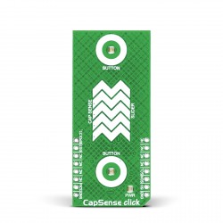
With Cap-sense click we offer you a low cost solution for you to go inside this technology. Click board caries the CY8C201A0 by Cypress which functionality is configured through an I2C. The user can configure registers with parameters needed to adjust the operation and sensitivity of the CapSense buttons and outputs and permanently store the settings.
The standard I2C serial communication interface enables the host to configure the device and to read sensor information in real time. The I2C address is fully configurable without any external hardware strapping.
Cap-sense click board have two buttons, two LEDs, one GPIO pin that can be configured by user and a five segment slider so you can explore the possibilities through the different configuration of the module registers and how different configuration can affect to the module behavior.
Example
We present the Cap-sense click example for PIC and AVR compilers all with well commented source code on Libstock.com or GitHub.com
Examples have two sources - the simple driver that implements the module's communication through the I2C bus and the other is a simple example of the clickboard functionality.
#define CY8C201A0_ADDRESS 0x00

void CY8_WrSingle( unsigned short wAddr,
                   unsigned short wData )
{
    I2C1_Start();                           // issue I2C1 start signal
    I2C1_Wr( CY8C201A0_ADDRESS );           // send byte via I2C1  (command to 24cO2)
    I2C1_Wr( wAddr );                       // send byte (address of EEPROM location)
    I2C1_Wr( wData );                       // send data (data to be written)
    I2C1_Stop();
}

unsigned short CY8_RdSingle( unsigned short rAddr )
{
    unsigned short rd;

    I2C1_Start();                           // issue I2C1 start signal
    I2C1_Wr( CY8C201A0_ADDRESS );           // send byte via I2C1  (device address + W)
    I2C1_Wr( rAddr );                       // send byte (data address)
    I2C1_Repeated_Start();                  // issue I2C1 signal repeated start
    I2C1_Wr( CY8C201A0_ADDRESS | 0x01 );    // send byte (device address + R)
    rd = I2C1_Rd( 0u );                     // Read the data (NO acknowledge)

    while ( !I2C1_Is_Idle() )
        asm nop;                            // Wait for the read cycle to finish

    I2C1_Stop();

    return rd;
}

void CY8_RdSeq( unsigned short rAddr,
                unsigned char *rcvData,
                unsigned long rLen )
{
    unsigned short i;

    I2C1_Start();                           // issue I2C1 start signal
    I2C1_Wr( CY8C201A0_ADDRESS );           // send byte via I2C1 ( device address + W )
    I2C1_Wr( rAddr );                       // send byte (address of EEPROM location)
    I2C1_Repeated_Start();                  // issue I2C1 signal repeated start
    I2C1_Wr( CY8C201A0_ADDRESS | 0x01 );    // send byte (device address + R)
    i = 0;

    while ( i < rLen )
    {
        rcvData[ i++ ] = I2C1_Rd( 1u );     // read data (acknowledge)

        while ( !I2C1_Is_Idle() )
            asm nop;                        // Wait for the read cycle to finish
    }

    rcvData[ i ] = I2C1_Rd( 0u );           // last data is read (no acknowledge)
    I2C1_Stop();
}

void CY8_WrSeq( unsigned short wAddr,
                unsigned char *wrData,
                unsigned long rLen )
{
    unsigned long i;

    I2C1_Start();                           // issue I2C1 start signal
    I2C1_Wr( CY8C201A0_ADDRESS );           // send byte via I2C1  (device address + W)
    I2C1_Wr( wAddr );                       // send byte (address of EEPROM location)
    i = 0;

    while ( i++ < rLen )
    {
        I2C1_Wr( wrData++ );
        Delay_22us();
    }

    I2C1_Stop();
}
#include "CY8C201A0.h"
#include "built_in.h"

sbit RST at LATE.B1;
sbit RST_Dir at TRISE.B1;

void MCU_Init()
{
    ANSELA = 0;
    ANSELB = 0;
    ANSELC = 0;
    ANSELD = 0;
    ANSELE = 0;
    RST_Dir = 1;
    TRISB = 0;
    TRISD = 0;

    I2C1_Init( 100000 );
    Delay_ms( 150 );
}

void CY8_Set_default_Mode()
{
    Delay_10ms();
    // Enable pins on B0,B1 and slider as CapSense
    CY8_WrSingle( COMMAND_REG, 0x08 );
    CY8_WrSingle( CS_ENABL1,   0x1F );     // Five pins will be used for Slider pads
    CY8_WrSingle( CS_ENABL0,   0x18 );     // Two pins will be used for Button pads
    CY8_WrSingle( GPIO_ENABLE0,0x03 );     // Three pins will be used as GPIO 2 for LED and 1 as GPIO2
    CY8_WrSingle( DM_STRONG0,  0x03 );     // Enables strong drive mode for GPIOs

    // Enable slider
    CY8_WrSingle( CS_SLID_CONFIG, 0x01 );

    // Configure slider resolution
    // Resolution = (SensorsInSlider - 1) * Multiplier
    // Resolution = 4 * 16.00 = 64
    // so the slider_val will be in range 0 to 64
    CY8_WrSingle( CS_SLID_MULM,   0x10 );
    CY8_WrSingle( CS_SLID_MULL,   0x00 );

    CY8_WrSingle( COMMAND_REG, 0x01 );     // Store Current Configuration to NVM
    delay_ms( 150 );

    CY8_WrSingle( COMMAND_REG, 0x06 );     // Reconfigure Device (POR)
    delay_ms( 250 );

    // Initial ON*OFF*ON LEDs (inverse logic 0-LED ON, 1-LED OFF)
    CY8_WrSingle( OUTPUT_PORT0, 0x00 );
    Delay_ms( 500 );

    CY8_WrSingle( OUTPUT_PORT0, 0x03 );
    Delay_ms( 500 );

    CY8_WrSingle( OUTPUT_PORT0, 0x00 );
}

void main()
{
    char            rd_slider[ 2 ];
    char            cs_status;
    unsigned int    slider_val;
    char            btn0st;
    char            btn1st;
    char            led0st      = 0;
    char            led1st      = 0;
    char            tgl0        = 0;
    char            tgl1        = 0;

    MCU_Init();
    CY8_Set_default_Mode();

    while( 1 )
    {
        cs_status = CY8_RdSingle( CS_READ_STATUS0 );
        btn0st = ( cs_status & 0x08 ) >> 3;
        btn1st = ( cs_status & 0x10 ) >> 4;

        // Check button 0
        if( btn0st == 1 )               // Button 0 is pressed
        {
            tgl0 =  1;                  // Update a toggle flag variable
        } else {

            if( tgl0 == 1 )             // Button 0 is pressed and released
            tgl0 = tgl0 | 2;            // Update a toggle flag variable
        }

        if ( tgl0 == 3 )                // Toggle flag is active
        {
            led0st = 0x01 ^ led0st;     // Update the LED status
//*         led0st = 0x02 ^ led0st;
            tgl0 = 0;                   // Reset toggle flag
        }

        // Check button 1
        if( btn1st == 1 )               // Button 1 is pressed
        {
            tgl1 = 1;                   // Update a toggle flag variable

        } else {

            if( tgl1 == 1 )             // Button 1 is pressed and released
                tgl1 = tgl1 | 2;        // Update a toggle flag variable
        }

        if ( tgl1 == 3 )                // Toggle flag is active
        {
            led1st = 0x02 ^ led1st;     // Update the LED status
//*         led0st = 0x01 ^ led0st;
            tgl1 = 0;                   // Reset toggle flag
        }

        CY8_WrSingle( OUTPUT_PORT0, 0x1C | led1st  | led0st );

        // Check for slider action
        CY8_RdSeq( CS_READ_CEN_POSM, &rd_slider, 2 );
        slider_val = rd_slider[ 0 ] << 8 | rd_slider[ 1 ];
        LATD = 1 << ( slider_val >> 3 );// Deviding slider_val(0-64) by 8 will give resolution 0-8
                                        //  which will then move 1(bit) across the portD LEDs (as you move over CapSense slider)
    }
}
Summary
Cap-sense is simple and very usefully technology. It can improve functionality, design and durability of your device, so if you are going to develop something new don't avoid using a technology like Cap-sense because it can bring many benefits with little risk.


