


Starting a New Project
With the development boards and 550+ Click board™ that Mikroe offers, just by adding the Go to Cloud (G2C) click you can adapt any development board and devices to the cloud.
Creating an account on the Click Cloud app is free of charge.
The Mikroe Go to Cloud (G2C) click offers the complete libraries and examples to get you started as quickly as possible in a few simple steps.
We’ll show you just one of the many scenarios in which you can use two different Click boards™ along with the Go to Cloud (G2C) clicks to make an IoT project.
This project demonstrates a simple example which shows how the Click Cloud can help in automatization of a certain operation. Let’s have two device nodes:
-
one that will serve as a sensor which will send its measurements to the cloud, and
-
the other one as an actuator which will receive the instructions FROM the cloud for performing a certain operation
The device nodes will interact through a rule engine, available on the Click Cloud.
The absolutely necessary precondition is that you have already created the account on the Click Cloud.
Out of HARDWARE components, for this 'Let’s make' project you’ll need:
-
1 x Thermo 7 click
-
1 x BarGraph click
-
2 x G2C click
Of course, having the ARM compiler and the programmer for Kinetis is a given.
The preparation
For the preparation, you will need to download the libraries for the aforementioned Click boards™ from Libstock:
As you are already accustomed, there are standard demo applications which can be used with every click for the sake of testing. If you wish so, you can upload these to the system and test the functionality of the BarGraph click and Thermo 7 clicks.
Besides the standard libraries, you’ll need to download and install the already created demo projects:
These demo projects already contain the source code which will make further steps and the demonstration easier.
Thermo 7 device node
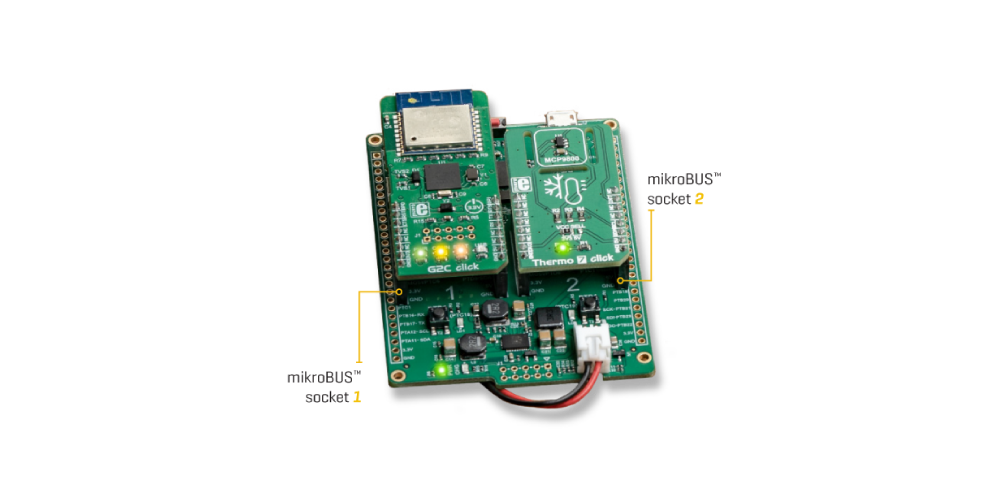
First, you will need to assemble the hardware. Let’s assemble the Thermo 7 device node which will, as you are assuming, send the temperature measurement data to the Click Cloud.
Thanks to the modularity provided by the Click boards™ and the mikroBUS™ socket, all you need to do is set the G2C click to the mikroBUS™ socket no. 1, and the Thermo 7 click to the socket no. 2.
Creating the device in the web application
After you’ve assembled the hardware components you will need to create the device on the cloud application which is equivalent to the hardware you just assembled. After you’ve logged in to the web application, you’ll need to:
-
Go to the Devices in the navigation menu
-
Click on Add device (the + icon), and then on Create Device
-
Choose Thermo 7 click from the drop-down list by clicking the Device manifest in the right side of the window
-
Click on the Next step
-
Assign the Device Name
-
Click Save
-
Copy and paste the Device key and Password which will appear on the screen, or use some of the options offered in the dialogue (Download/Send via email)
-
Click OK
Then, you will be taken back to the list of devices where you can see the newly - created device with the name you assigned to it in step no. 5. Just for the test, you can click on it to open it and to see the details about the device. You’ll notice the Data tab. If you click on it you’ll see that the Last Value field is empty at the moment, which is expected as the device has just been set and it has never received any data before.
Program the Thermo 7 node device application
In this step, you will create the device node embedded application, which will send some data toward the web app (more precisely, to the device we’ve just created in the previous step) for the first time. All the steps we’ve enlisted here are performed from IDE only.
-
Install the Thermo 7 Cloud demo package which contains the code for the demo application
-
Open the project from the Examples tab
-
Change the parameters for the Wi-Fi network in the src code of the demo application
(g2c_netwrorkName, g2c_networkPassword ) -
Paste the credentials which we’ve received in the step no. 7 of the previous section
(g2c_devKey, g2c_devPass ) -
Rebuild the demo by clicking the “rebuild all” (Alt + F9)
-
Program the MCU on the system (F11)
After this, the first data will start arriving at the cloud. If you go back to the web browser and repeat the operations from the last paragraph of the previous section, you’ll see within the details about the device its online status, and that now in the Data field there is some data. These are the measurements from the Thermo 7 node.
BarGraph device node
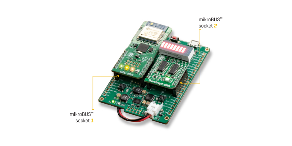
This device node, as we’ve already mentioned, will receive the data from the cloud and display them on the LED bar. The device needs to be prepared by inserting the G2C click to the mikroBUS™ socket no. 1, and the BarGraph click to the socket no. 2.
Creating the device in the web application
The steps for creating the device are the same as for the Thermo 7 node, with the difference being that you need to choose the BarGraph click from the drop-down list and assign a name to the device which is different from the previous device (Thermo 7 node). After creating the device and returning to the devices list, if you look at the details about the device by clicking on it, you’ll notice that there is no Data tab, contrary to the Thermo 7 node. The reason for this is that this device is not sending any measurements to the cloud, but instead, the cloud controls the behavior of this device – we will define the behavior on the section titled Configuration of the Rule Engine.
Programming the BarGraph node device application
In this step, we will create the device node embedded application which will receive some data from the web app. All the enlisted steps are performed from IDE only.
-
Install the BarGraph cloud demo package which contains the code for the demo app
-
Open the project by going to the Examples tab
-
Change the parameters for the WiFi network in the src code of the demo application
( g2c_networkName, g2c_networkPassword ) -
Paste the credentials which we’ve received in the step no. 7 of the previous section
( g2c_devKey, g2c_devPass ) -
Rebuild the demo by clicking on Rebuild All (Alt + F9)
-
Program the MCU on the system (F11)
After this, if you check out the details about the device on the web application, you’ll see that the device is now online, which means it’s ready to accept the actuation from the cloud.
The configuration of the Rule Engine
After entering the Rule Engine by clicking on Rules in the Navigation menu, after you click on Add Rule + icon, you will enter the Create Rule dialogue. You need to define the condition under which a certain operation will be performed – in this case, the change of the value which the BarGraph shows depending on the temperature measured. The definition of the conditions is done in the When section by the following:
-
Click on the New condition – Add
-
Choose the Thermo 7 device by the name which you assigned in the step no. 5 while creating the Thermo 7 node.
-
For the Field Property choose the Thermo 7
-
Set the operator to the Lower than
-
Static value
-
Type in 20 (degrees)
This way you can set up that a certain operation will be performed in the case that the temperature on the Thermo 7 device drops under 20°C. In the next step, we will show which is the operation we just mentioned. Click on the Next step. After this, a section titled Then will open, where you will do as follows:
-
Choose “Set / Actuate” for the Action Type
-
Choose the device by the name assigned while creating the BarGraph device
-
Choose the BarGraph actuator
-
Set the value 1
You’ve just defined the operation which will be performed in case the temperature drops below 20°C, which is that the value of the BarGraph is set to 1, i.e. to illuminate only one field. After clicking on the Next button, a dialogue will open in which you will need to:
-
Describe the Rule – for example, “Turn on 1 Bar”
-
Write the short description of the rule
-
Turn on the rule
-
Click on the Create Rule
With this, you’ve completed the operation of creating one rule. In the same way, you can define the rest of the ranges. For example, you can create another rule for which you can set up so that in case the temperature is - or is over 10°C, but lower than 15°C, there should be 2 LED bars on the BarGraph click. The bottom line would be that you need to create the rule for all the 10 statuses which the BarGraph can display. It’s up to you which temperature ranges you will set.
Conclusion
The final result will be the BarGraph click which shows the momentary measurements of the temperature at the location where the Thermo 7 device is set. The precondition is, of course, availability of a Wi-Fi network at the location where you’re measuring the temperature. During this 'Let’s make' project, you’ve probably noticed other options such as choosing other actions to be performed – sending an email for example, or a push notification. It’s also important to stress that it’s possible to define custom devices by creating the manifests of your choice.
It’s also important to emphasize that thanks to the mikroSDK™, the already created projects can be used for the development systems by your choice, by simply selecting the system from the mikroBUS™ API. We’ve chosen clicker 2 system because of the design of that system and the jack for the Lithium-Ionic battery which provide a degree of liberty, in the sense that the device doesn’t have to be near the power supply source.